No I have not. Took a detour at the 725D exit off ramp. .
Are you making any headway with that one?
Are you making any headway with that one?
It too has potential because of the older opamps used in many places. But need schematic to know what and where everything of interest might be. I have had no luck in finding a service manual for it. So I have that project on hold until I get a service manual.
_RNM
A-P opamp?
Dimitri --- what opamp is used in the A-Precision's oscillator?
Thx - RNMarsh
Richard, they specify THD+N in 22kHz bandwidth:
Analog generator residual THD+N At 1 kHz _(0.00025% + 1.0 μV) [–112 dB], 22 kHz BW
Analog analyzer Residual THD+N: At 1 kHz _(0.00025% + 1.0 μV) [–112 dB], 22 kHz BW
Dimitri --- what opamp is used in the A-Precision's oscillator?
Thx - RNMarsh
The AD797 is probably not stable when used in a basic inverting integrator (or any other with substantial capacitive feedback) application. Don't know how AP solved this, but I have used a small resistor (150-220 Ohm) in series with the inverting input. If you can't stand the noise penalty, parallel the resistor with a wideband inductor.
Samuel
Samuel
Ok... Thx SG. Thats what I am looking for -- practical app info. Not trade secrets.
I've seen buffers driving osc opamps input -- presumably to provide low source Z on the osc opamp input (?). But a small R ll L is easy to try if I run into trouble.
Thx-RNMarsh
I've seen buffers driving osc opamps input -- presumably to provide low source Z on the osc opamp input (?). But a small R ll L is easy to try if I run into trouble.
Thx-RNMarsh
Last edited:
Hi,
Having zero experience with low distortion oscillators, but after reading this thread I was thinking that this could be a candidate for a detector.
Precision Envelope Detector with 0.032% Total Harmonic Distortion
It was mentioned a few years ago on the LTspice forum by Mike Monett
Ite
Having zero experience with low distortion oscillators, but after reading this thread I was thinking that this could be a candidate for a detector.
Precision Envelope Detector with 0.032% Total Harmonic Distortion
It was mentioned a few years ago on the LTspice forum by Mike Monett
Ite
Well I recieved the AD797 today and went direct to the KH4402B and yanked the LT1468 and put the AD in its place as the oscillator. yes, i added the 50pf.
Here is the result in a nut shell --> The noise dropped about 6dB and the THD+N dropped 3-4 dB's from 1KHz to 10Khz. Not a huge change but I'll take it. The oscillator THD+N is .00009- .0001% at 1KHz and .00015% at 10Khz from the direct out from the oscillator port (7v rms). Adjust the 10-turn AVC trim pot (R145) for lowest THD at 10Khz.
The lowered noise floor is now showing me junk I had not seen before (like ps harmonics so i beefed up the filtering on the ps) and allows me to see the individual harmonics better.
Thx-RNMarsh
Last edited:
")
AD797 osc for KH4402B -
here is what the opamp change produced -->
The noise is lower as compared to previous plots I've shown and the higher harmonics are uncovered. The ref level peak on the left is -110dB. The 2H and 3H are about a little more than 20dB below reference. The higher harmonics are more than -140dB. The noise floor shown is at -145dB. [1KHz 7v p-p; 400Hz and 100KHz filter In]

Thx-RNMarsh
here is what the opamp change produced -->
The noise is lower as compared to previous plots I've shown and the higher harmonics are uncovered. The ref level peak on the left is -110dB. The 2H and 3H are about a little more than 20dB below reference. The higher harmonics are more than -140dB. The noise floor shown is at -145dB. [1KHz 7v p-p; 400Hz and 100KHz filter In]
Thx-RNMarsh
Last edited:
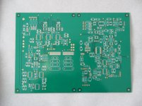
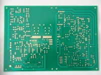
SVO boards
My long awaited PCBs have arrived from China.
These are development boards for my SVO design.
I panelized them to save on setup charges.
Now I have a back log of projects to catch up on since all the boards I ordered have arrived at once from various parts of the world.
Cheers,
My long awaited PCBs have arrived from China.
These are development boards for my SVO design.
I panelized them to save on setup charges.
Now I have a back log of projects to catch up on since all the boards I ordered have arrived at once from various parts of the world.
Cheers,
Attachments
The lowered noise floor is now showing me junk I had not seen before (like ps harmonics so i beefed up the filtering on the ps) and allows me to see the individual harmonics better.
You might wish to consider swapping out the 7815/7915 for 317/337 with 10uF on the adjust pin. This will knock down the noise again. (My 4402 was inexpensive compared to the ones you see on EBay as the positive regulator had failed.)
The NE5534 on my 4402B are not socketed, so mine is pretty much stock.
here is what the opamp change produced -->
The noise is lower as compared to previous plots I've shown and the higher harmonics are uncovered. The ref level peak on the left is -110dB. The 2H and 3H are about a little more than 20dB below reference. The higher harmonics are more than -140dB. The noise floor shown is at -145dB. [1KHz 7v p-p; 400Hz and 100KHz filter In]
View attachment 337099
Thx-RNMarsh
Hi Rick,
Can you throw up some of the previous plots along with this one for comparison?
Today i tried the AD797 in two other makes/models. I got mixed results. In the KH4400, it did not reduce the THD+N. I think the circuit Z's and other elemnets are dominating . But the numbers are still pretty good --- typically .00035% using the LT1468.
Then i tried the AD797 in the HP 339A 's oscillator's opamp and retuned. I went back and forth a few times as the tuning of 3 seperate pots/trim interact and there is some compromise over the range of 1KHz -10KHz. But all in all the LT1468 is staying in as osc. The AD797 with these circuit impedances caused the THD to be higher. Splitting the THD+N with the adjustments leaves me with .00025% at 1KHz and .00065% at 10KHz. If tuning for best THD numbers at 1KHz, you can get under .0001%... but then at 10KHz it is much higher.
Note both the 339A and the 4400 use the jFEt as a control element. The 4402B does not use a jFET.
Thx-RNmarsh
You might wish to consider swapping out the 7815/7915 for 317/337 with 10uF on the adjust pin. This will knock down the noise again. (My 4402 was inexpensive compared to the ones you see on EBay as the positive regulator had failed.)
The NE5534 on my 4402B are not socketed, so mine is pretty much stock.
I have only tried adding more filter caps and a .47mfd bridge cap. Slightly (1-2dB noise improvement only). I have not tried changing the IC regulators.
BTW - what opamp is being used in your 4402 oscillator? Have you tried changing it, if it is still a 318?
I got .00015% with the LT1468. Lower now with the change to AD797....To just under .0001% THD+N.
-Richard
Last edited:
My long awaited PCBs have arrived from China.
These are development boards for my SVO design.
I panelized them to save on setup charges.
Now I have a back log of projects to catch up on since all the boards I ordered have arrived at once from various parts of the world.
Cheers,
Thats great news. Looking forward to the results.
-Richard
Thanks for posting the picture of the PCB. I can appreciate the effort involved in the design. I am interested in how the frequency range switching is achieved. I can see what looks like pads for the connections in the middle of the PCB so would like to see pictures of the assembled board.My long awaited PCBs have arrived from China.
These are development boards for my SVO design.
I panelized them to save on setup charges.
Now I have a back log of projects to catch up on since all the boards I ordered have arrived at once from various parts of the world.
Cheers,
- Home
- Design & Build
- Equipment & Tools
- Low-distortion Audio-range Oscillator