Insides of Shibasoku oscillator
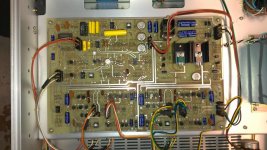
I pulled my other Shibasoku oscillator, 590AR, from storage and took a photo of its insides. This is the top view. The bottom has the frequency and level networks. Both this the AG15 and AG16 are remote controllable. This older one uses a parallel interface, the newer ones GPIB, otherwise they are identical.
There are several opamps, all TL07X types. There is also an LM710CH (The can) and an MC1495. I suspect the AGC uses the small metal can device 2SK15 (??). The tree trimmers are +1 dB, 0 dB and -1 dB for some function. My guess would be a steering for the AGC so the active part doesn't need much range to stabilize it. The supplies are +/-30V.
Attachments
Last edited:
Shibasoku 725 insides
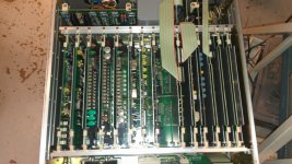
And here is why you won't want to duplicate this thing.
There are a jillion PCB's and each have a bazillion relays. When Richard gets the manual calibration should be simple since the key nodes and adjustments are clearly marked in good English.
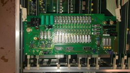
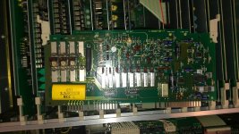
The detector board is actually the input board. The device in the middle is a dual Jfet I think. The relays handle the input attenuation.
Design was an enormous undertaking but its still in the lineup 30 years later.
And here is why you won't want to duplicate this thing.
There are a jillion PCB's and each have a bazillion relays. When Richard gets the manual calibration should be simple since the key nodes and adjustments are clearly marked in good English.
The detector board is actually the input board. The device in the middle is a dual Jfet I think. The relays handle the input attenuation.
Design was an enormous undertaking but its still in the lineup 30 years later.
Attachments
And here is why you won't want to duplicate this thing.
There are a jillion PCB's and each have a bazillion relays. When Richard gets the manual calibration should be simple since the key nodes and adjustments are clearly marked in good English.
The detector board is actually the input board. The device in the middle is a dual Jfet I think. The relays handle the input attenuation.
Design was an enormous undertaking but its still in the lineup 30 years later.[/QUOTE
Considering all the board artwork was done by hand too.
I pulled my other Shibasoku oscillator, 590AR, from storage and took a photo of its insides. This is the top view. The bottom has the frequency and level networks. Both this the AG15 and AG16 are remote controllable. This older one uses a parallel interface, the newer ones GPIB, otherwise they are identical.
There are several opamps, all TL07X types. There is also an LM710CH (The can) and an MC1495. I suspect the AGC uses the small metal can device 2SK15 (??). The tree trimmers are +1 dB, 0 dB and -1 dB for some function. My guess would be a steering for the AGC so the active part doesn't need much range to stabilize it. The supplies are +/-30V.
It appears the oscillator(s) are all descrete transistors design.
I just posted the first rev on the QA400 interface here: http://www.diyaudio.com/forums/equipment-tools/231401-quantasylum-qa400.html#post3396418 We should probably move discussions about the QA400 there.
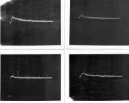
Attached are some harmonic pictures of 4 ultra-low distortion oscillators. The noise from the oscillators is between 140-150dB (no averaging used -- eg FFT). The ShibaSoku 725 notch shows itself at -155-160dB. All Harmonics are below -130, worst case harmonics. Typically -140 or more. The AG16 looks like it has higher harmonics but its just the noise floor is 10dB lowe than the others... and fairly flat (not rising at lower freq end).
Top left is Viktor's 1Khz, Top right KH 4402B, Bottom left is HP 339A, and bottom right is AG16. All excellent. However the HP339A cannot keep its lowest thd at other freqs as well as the others without individual fine tuning.... Thx-RNMarsh
Top left is Viktor's 1Khz, Top right KH 4402B, Bottom left is HP 339A, and bottom right is AG16. All excellent. However the HP339A cannot keep its lowest thd at other freqs as well as the others without individual fine tuning.... Thx-RNMarsh
Attachments
Last edited:
EMU 0204 mods
Hi Guys,
I've done some mods to the EMU 0204 to improve dynamic range and lower the measurement noise floor. I started a new thread for this because others have commented to me that it's too difficult to plow through hundreds of post to find things. As it is for the work on the 339A.
Have a look.
http://www.diyaudio.com/forums/equipment-tools/231426-emu0204-mods-fft-measurements.html#post3396870
Cheers.
Great, Davada --- More spin-off's. Demians work can also apply to EMu or others. I am interested in both. I think the HP339A is done. It is what it is. Can be useful to many. But we would need a notch filter and FFT. All together, with a low cost ultra-pure oscillator source, a DIY'er can measure without breaking the bank. Thus, these spin-off forums. Some already before us.
We might summarize where to find the How-To changes for the 339A... which line #'s. Then, it wont be so arduous for others as it was for us to do it first for them.
And, I have reached my goal of at least -140 THD+N or better but thru other hardware and more $$. I wouldnt have got to that point without first exploring the 339A which lead to my own spin-off directions.
Thx all -- Richard Marsh
Last edited:
I discovered this project last night and I think it can be of extreme interest here:
An Audio T.H.D. Analyser
I don't think the author follows this forum.
An Audio T.H.D. Analyser
I don't think the author follows this forum.
yes, i have read it. It is now, for me, the noise of the signal generators that limits the THD tests. I have a system noise floor that greatly exceeds the source noise ----
The analyzer goes to .0003% Full Scale (-110dB) and reads accurately 20 dB below that on its front panel meter. On its residual monitor output, I can go 90dB below that or -90 + -110dB for a -200db view of the world.... with FFT from EMU mods, another 140 + 110 = -250 dynamic range ref 1 volt [without considering the noise floor of the monitor output]. The noise of the best signal generator sources is at -140-150dB. And their harmonics barely show above their noise levels. So this is the current limits with all the tricks we can muster. My measurement noise floor is well below that.... another 40dB lower, at least.
Now we can go testing those commercial and DIY amplifier circuits and test passive parts, magnetic affects etc without test equipment spurious signals and dynamic range limitations for ACCURATE THD and THD+N measurements.
Next spin-off forum might be a signal generator with super low thd AND much lower noise levels...... but then we might have to use LN.
Thx-RNMarsh
Last edited:
yes, i have read it. It is now, for me, the noise of the signal generators that limits the THD tests. I have a system noise floor that greatly exceeds the source noise ----
The analyzer goes to .0003% Full Scale (-110dB) and reads accurately 20 dB below that on its front panel meter. On its residual monitor output, I can go 90dB below that or -90 + -110dB for a -200db view of the world.... with FFT from EMU mods, another 140 + 110 = -250 dynamic range ref 1 volt [without considering the noise floor of the monitor output]. The noise of the best signal generator sources is at -140-150dB. And their harmonics barely show above their noise levels. So this is the current limits with all the tricks we can muster. My measurement noise floor is well below that.... another 40dB lower, at least.
Now we can go testing those commercial and DIY amplifier circuits and test passive parts, magnetic affects etc without test equipment spurious signals and dynamic range limitations for ACCURATE THD and THD+N measurements.
Next spin-off forum might be a signal generator with super low thd AND much lower noise levels...... but then we might have to use LN.
Thx-RNMarsh
Double check your arithmetic. I suspect the thermal noise floor will limit before -200 dB. Its clear that the ShibaSoku stuff gives an impressive windo into steady state distortion. I also have the Radiometer CLT-1 which is good for -160 dB or better for the 3rd harmonic of 10 KHz. I have two so I can measure through a 4 terminal device. I have yet to see an active device that needs this level of resolution.
Both the CLT-1 and the 725 suggest that passive filters may be necessary to get below -110 measurements on a regular basis. If we can come to a practical solution for a generator/source and a filter I'll see about grafting them to the QA400 as an indicator.
Double check your arithmetic. I suspect the thermal noise floor will limit before -200 dB.
Of course it will. -200db is in theory. But i have not seen it just yet where the equipments limits are. The opamps used in the ulta-low distortion generators are some of the lowest made (<5nV) and I see theirharmonic lower limits at -130/-140dB. So where is the test system's limit? -160 and beyond is quit do-able with this equipment
.
I can measure the noise out of the monitor residual port and that is one limit where I wont be able to go lower. I'll let you know.
BUT ADC with FFT averaging for noise reduction and notch filtering the fundemental gets to a floor of -140 is excellant but not as low as this here. If this ShibaSoku ever breaks, it'll cost too much to repair it... a refurbished one was recently selling for $12K.
Never-the-less, with adc/fft and a noise and residual generator of -140 is super good by any account. Few amps et al are that good so its a great and relatively cheap way to go. Thats the current development of test equipment via PC control and data gathering/plotting etc.
Other's here are working on new approaches using DSP filters to measure thd which has great potential and promise. That would also allow for swept tests below current A-Prec levels of .0003% at a much lower cost.
This has started many people thinking of better ways/improved ways and new ways. Only good can come of it.
But we still need better generators to be below -140 THD+N... my original goal.
Thx-RNMarsh
Last edited:
I'm curious what the SW-OPA might do in an oscillator role. Or a ultra low noise opa like the LT1115, perhaps? With all the R and C's scaled for lowest noise. Even a JC MC pre-pre circuit for an oscillator. Or tricks to cancel thd along with very low noise to make a better generator source. What can be done? Can it be done? Lower noise levels for ultra-low distortion oscillators.
None of the current oscillators tested here use the latest and greatest opamps.
Thx -RNM
None of the current oscillators tested here use the latest and greatest opamps.
Thx -RNM
Last edited:
I'm curious what the SW-OPA might do in an oscillator role. Or a ultra low noise opa like the LT1115, perhaps? With all the R and C's scaled for lowest noise. Even a JC MC pre-pre circuit for an oscillator. Or tricks to cancel thd along with very low noise to make a better generator source. What can be done? Can it be done? Lower noise levels for ultra-low distortion oscillators.
Thx -RNM
Hi Rick,
If you could figure out a way to add more inverting stages to an SVO increasing the LP order the distortion would drop but the noise might be higher.
Can we do an osc with multiple stage SV filters?
If you could figure out a way to add more inverting stages to an SVO increasing the LP order the distortion would drop but the noise might be higher.
You probably mean more integrator stages. I've looked into this but so far have not come up with a suitable result.
Samuel
I'm curious what the SW-OPA might do in an oscillator role. Or a ultra low noise opa like the LT1115, perhaps? With all the R and C's scaled for lowest noise. Even a JC MC pre-pre circuit for an oscillator. Or tricks to cancel thd along with very low noise to make a better generator source. What can be done? Can it be done? Lower noise levels for ultra-low distortion oscillators.
None of the current oscillators tested here use the latest and greatest opamps.
Thx -RNM
Even the Brisbois (Christmas bulb) oscillator works amazingly well (~-120dB 2nd and 3rd) with the AD797. The ADA4898-1 not so well (CM effects). OPA627 oscillated.
Last edited:
You probably mean more integrator stages. I've looked into this but so far have not come up with a suitable result.
Samuel
Yes I mean integrator stages.
- Home
- Design & Build
- Equipment & Tools
- Low-distortion Audio-range Oscillator