THD+N = -105db
About average these days. Have others in-house here that are equal. But, Thx- RNM
24bit should do better, theoretically. I've seen some multibit 18bit AD chips that do that figure (thinking to get one actually)...
Borrow some of the techniques used in the ShibaSoku AD725D.
I just had a brief look at the patent, but I'm pretty confident it too relies on an analog notch filter ahead of further processing. Whatever smart things we do later, the notch filter will limit performance.
I spotted a few small boxes designed for EMI RF shielding which come with BNC connector at each end. The size is quite limited. Do you suppose your notch filter can squeezed onto a small very board? The boxes are expensive but I think well suited for this purpose.
I've designed the PCB for a specific case (Mouser 546-1457C801E). I'm not sure how much smaller you can get--quality caps/resistors simply have their size. You can replace the 3x 10x parallel caps with 3x single ones to save some space, but you should then match them to get best notch depth.
Samuel
I have traced part of the ciruit of a ShibaSoku AD725C and it has 3 cascaded Bridged T Notch Filters. They each have 4 frequency ranges and the trim is with precison scaled (x2) resistors switched in using reed relays, lots of them. I haven't traced the frequency hetrodying part.
I'm not sure how much smaller you can get--quality caps/resistors simply have their size. You can replace the 3x 10x parallel caps with 3x single ones to save some space, but you should then match them to get best notch depth.
Samuel
With the two trim technique I seem to be able to walk to a >70dB null even with just 2 single and one 2-parallel caps. I think the pots can be made a small enough portion of the resistor to not be an issue.
My sincere apologies for repeating myself every 20 pages or so in this thread, but quoting direct analog distortion measurements at the -150 dB level is simply not credible at the current state of the art (unless someone gives a detailed, repeatable proof how he verified measurement integrity to this level, which is pretty unlikely).
I am inclined to agree. While I have confidence in the -165 dB+ numbers I get from the CLT-1 that is a very special case and not broadly useful. I have two and have used them for two port devices (pots) but I would not extend that to amplifying devices at present. Maybe you can shed some light on how Weiss would verify the distortion numbers quoted for this amp module: http://www.weiss-highend.ch/op-amp/documents/flyer_bipolar_r1.pdf . They seem too good to be true. For $130 ea. they could be a great value. That's close to the internal cost for the modules I designed for Nuforce.
The service manual is still available and it describes the operation of the fundamental notching in detail. Quite clever, they quadrature detect the residual fundamental and tune out both I and Q components. Maybe we are talking about different things, there was no A/D in 1985 that even remotely could do -100dB.
EDIT - I see, THD + N, I agree a useless metric.
Well that settles it... Then I conclude mine is broken in some way (notch not working?). Who knows whats wrong because A-P wont service it. Too old. Thus, I took it with me to Asia -- to have their A-P service people who will still work on old ones. meanwhile -----
Last edited:
24bit should do better, theoretically. I've seen some multibit 18bit AD chips that do that figure (thinking to get one actually)...
This is exactly what threw me off. I've been sitting on the side lines for years with the impression they are much better than implied. Surprise! Surprise! Surprise! It hasnt taken me too long to find this out and coming up to speed.
Now, I do have a passive Notch filter -- used it on 339A oscillator a few million pages back. It's the variable freq B&Kjaer Type 1607. BUT just like with the oscillators... I want to keep the testing time down and the use of equipment all to a minimum. So a super osc with really low thd and an active notch so that no calculations are needed and less over-all lash-ups to deal with. Trying to simplify now that i know what's going on and what is needed and why.
How good can an active Twin-T be for the project?
Thx-RNMarsh
Last edited:
I just had a brief look at the patent, but I'm pretty confident it too relies on an analog notch filter ahead of further processing. Whatever smart things we do later, the notch filter will limit performance.
I've designed the PCB for a specific case (Mouser 546-1457C801E). I'm not sure how much smaller you can get--quality caps/resistors simply have their size. You can replace the 3x 10x parallel caps with 3x single ones to save some space, but you should then match them to get best notch depth.
Samuel
This much smaller.
Attachments
I have several of those on my bench. They are difficult to work inside of. You could graft a filter into one using point to point wiring since there aren't many parts. It would need to be adjustable after assembly since drift is inevitable. I would use these http://www.vishay.com/docs/57014/6.pdf and really good trimmers. The Vishay foil ones do fit.
My experience with the active twin-t is that 40dB of fundamental attenuation is enough, but I like to use 60dB to be sure. I'm at the point where I don't know if it's the active filter or the oscillators I have that are my limiting factors for spur amplitudes. I really want to know, but I need a 1kHz oscillator that I know has all spurs at least -150dBV in order to verify. If anyone can assure me that Victor's oscillator will do that, then I'm all over it.
My experience with the active twin-t is that 40dB of fundamental attenuation is enough, but I like to use 60dB to be sure. I'm at the point where I don't know if it's the active filter or the oscillators I have that are my limiting factors for spur amplitudes. I really want to know, but I need a 1kHz oscillator that I know has all spurs at least -150dBV in order to verify. If anyone can assure me that Victor's oscillator will do that, then I'm all over it.
Hi Dick,
I don't know about -150dB but they are stunningly quiet.
Still waiting on some decal material to label the case for the TT. Once I have that the TT should be assembled and I'll send you some measurements.
John Curl suggested using a shunt cap to add an extra -6 dB/octave reduction in the harmonics of the source. I can't say that would be enough to address these issues or would even work at this level.
As a passive LP?
Sorry for not being clearer, yes.
Hi Demian,
You can try this. It does work but with a variable tuned oscillator it means one more circuit stage to tune.
With the two trim technique I seem to be able to walk to a >70 dB null even with just 2 single and one 2-parallel caps. I think the pots can be made a small enough portion of the resistor to not be an issue.
It all depends on what trim range, operating level and distortion contribution we're looking for. I'm just saying that the wiper contact resistance can be really, really bad (that applies even for the bulk metal trimmers--the $$$ I've spent for those were a complete waste), depends on the position, varies a lot from specimen to specimen and may go bad over time. So for stuff approaching -140 dB I'm inclined to prefer selected parallel resistors to trim the center frequency to its nominal value. If trimmers are included, it might be helpful to arrange them such that one end is at (virtual) ground if possible--so one could measure their distortion contribution in isolation.
Maybe you can shed some light on how Weiss would verify the distortion numbers quoted for this amp module: http://www.weiss-highend.ch/op-amp/d...bipolar_r1.pdf . They seem too good to be true. For $130 ea. they could be a great value. That's close to the internal cost for the modules I designed for Nuforce.
The quoted figure is the input referred harmonic distortion voltage. This is quite easily measured by running the amp at high noise gain, and subtracting the noise gain from the measurement. Same trick as I've used for the opamp measurement series (although I did not subtract the noise gain there), and what TI uses for their IC opamps.
Samuel
Last edited:
Which version of the trimmer? My experience has been much better but none of mine are less than 10 years old.I'm just saying that the wiper contact resistance can be really, really bad (that applies even for the bulk metal trimmers--the $$$ I've spent for those were a complete waste), depends on the position, varies a lot from specimen to specimen and may go bad over time. Samuel
I see, that is measured in the way TI, Burr Brown, AD and National do it. Probably the only way to measure such low levels of distortion.The quoted figure is the input referred harmonic distortion voltage. This is quite easily measured by running the amp at high noise gain, and subtracting the noise gain from the measurement. Same trick as I've used for the opamp measurement series (although I did not subtract the noise gain there), and what TI uses for their IC opamps.
Samuel
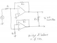
Awhile back i suggested taking oscillator distortion and inverting it and adding it back to cancel distortion. No takers. One way is as a unbal to bal converter using a bridge configuration to cancel thd... see below;
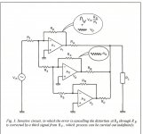
And the other is an iteritive circuit (using unbal/unbal). This can be used as the basis to make an oscillator of zero distortion. trim the values to null output thd. see below;
Pre-amplifier and power amp circuits can be made this way as well - using the error take-off point to cancel thd. It overcomes the basic limitation of neg fb which is - increasingly limited open loop gain with increasing freq. [Very low thd at very high freq can be accomplished this way]
[invented by A.M.Sandman] Thx RNMarsh


Last edited:
This is much smaller.
I use those for some simple circuits like R-R attenuators, RC filters or diode clamps. I agree with Demian that these are pretty tight for a notch filter, but it might work out with some care.
Which version of the trimmer?
1248W--larger versions probably have lower wiper contact resistance.
Samuel
This can be used as the basis to make an oscillator of zero distortion.
It might theoretically reduce amplifier distortion contribution towards arbitrary low levels, but it does nothing whatsoever about passives, layout effects, contribution from multiplier and level detector ripple... These are the real challenges.
Samuel
- Home
- Design & Build
- Equipment & Tools
- Low-distortion Audio-range Oscillator