Here is a really good approach to measuring the voltage using sampling techniques. http://www.home.agilent.com/upload/cmc_upload/All/Swerleins_Algorithm.pdf?&cc=US&lc=eng I don't think you need to go to the 3 ppm capability of the HP3458 to get value from this and if you had both level and frequency you could steer both to the desired values with a PIC or Arduino. (Linuxworks, where are you?)
Last edited:
It doesnt look too unwieldly and a pcb is already made to try it with. Now... what is the goal, again? The cause of thd that this is going to affect a reduction? Just checking... sort of a resync operation. -RNM
Hi Rick,
The FFT calculates and holds the peak. The peak is compared to a reference level and then
output to an integrator. The integrator's job is to find the DC value output to the multiplier which satisfies the loop requirements for the reference output level. The PIC would output a value to a DAC connected to the lamp drivers.
We only need a single frequency output from the FFT. Only the bins closet in to the FR are needed and anything that spills into adjacent bins ,AKA buckets, can be added back the FR peak. Since there is only one frequency of interest we can allow the FFT to wrap around the nyquist. It will show up as a lower alias frequency peak. Therefore sample rate limit of the PIC's ADC is not really a problem.
The question is how low a sample rate can we use?
The number of samples sets the number of bins. The fewer bins means more bandwidth is crammed into one bin including noise.
The second question is how few number of samples can we get away with and still have a reasonable accuracy. There is also the question of bit depth. Is 10 bits enough.
The smaller the FFT is the faster it computates.
The project in the link is a toy not an instrument.
I,m no expert on FFT so if anyone is more knowledgeable please comment.
Microchip has a white paper on using FFT as a peak detector.
I already have a development board for the PIC18F2455 which is the same as the PIC18F4550 just fewer IO ports.
Last edited:
Here is a really good approach to measuring the voltage using sampling techniques. http://www.home.agilent.com/upload/cmc_upload/All/Swerleins_Algorithm.pdf?&cc=US&lc=eng I don't think you need to go to the 3 ppm capability of the HP3458 to get value from this and if you had both level and frequency you could steer both to the desired values with a PIC or Arduino. (Linuxworks, where are you?)
Hi Demian,
Dead link there.
Hi Rick,
The FFT calculates and holds the peak. The peak is compared to a reference level and then
output to an integrator. The integrator's job is to find the DC value output to the multiplier which satisfies the loop requirements for the reference output level. The PIC would output a value to a DAC connected to the lamp drivers.
Something similar to this I figure ShibaSoku harmonic distortion analyzer is doing... displays the individual harmonics peaks from an FFT was my guess. -RNM
Something similar to this I figure ShibaSoku harmonic distortion analyzer is doing... displays the individual harmonics peaks from an FFT was my guess. -RNM
From it's description I think the Shibasoku is a heterodyne process. It's a very sophisticated selective voltmeter.
But since no one has a service manual for it who knows.
Cheers,
You could do this, then, with an HP 3586 Selective Level Receiver programmable via the HP-IB.From it's description I think the Shibasoku is a heterodyne process. It's a very sophisticated selective voltmeter.
But since no one has a service manual for it who knows.
Cheers,
From it's description I think the Shibasoku is a heterodyne process. It's a very sophisticated selective voltmeter.
But since no one has a service manual for it who knows.
Cheers,
Lock-in amplifier principle? I've been looking at some PAR units, but not sure if it is worth the hassle.
jan
From it's description I think the Shibasoku is a heterodyne process. It's a very sophisticated selective voltmeter.
But since no one has a service manual for it who knows.
Cheers,
AFAIR you are close, I once actually had a manual
 . I posted those parts and literally as the letter dropped into the bin I overheard the postmaster warning the next customer not to put anything non-flat in the generic mail box, hopefully it won't jam the automatic sorter. Keep an eye out, there are plenty more.
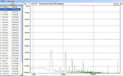
Here's my plot of the PV/FET circuit, a 1500/100 Ohm bridge, nulled against another 1500 Ohm resistor and the FET (J310) tuned to 100 Ohms. The seconds can be nulled to almost the noise (I used .033u across the PV don't know how low you can go). This is at ~.9V p-p on the FET, if the distortion is low order it should drop dramatically (60dB/dec) at lower levels.
This is about as good as I could null the fundamental stepping 1mV or so at a time on the PV drive (100 Ohm in series with the LED).
This is about as good as I could null the fundamental stepping 1mV or so at a time on the PV drive (100 Ohm in series with the LED).
Attachments
AFAIR you are close, I once actually had a manual
LOL.
I got ____ for that once too.
It's about postage not the machine jamming.
I mailed ordered some T03 can trans years ago. The guy stuck them in one of those padded flat packages. When I got them the pins were bent flat against the case. Maybe they go through a roller at the sorting facility.
Last edited:
Lock-in amplifier principle? I've been looking at some PAR units, but not sure if it is worth the hassle.
jan
Hi Jan,
You have giving a very interesting idea for a peak detector similar to lock in amplifier.
Thanks,
Here's my plot of the PV/FET circuit, a 1500/100 Ohm bridge, nulled against another 1500 Ohm resistor and the FET (J310) tuned to 100 Ohms. The seconds can be nulled to almost the noise (I used .033u across the PV don't know how low you can go). This is at ~.9V p-p on the FET, if the distortion is low order it should drop dramatically (60dB/dec) at lower levels.
This is about as good as I could null the fundamental stepping 1mV or so at a time on the PV drive (100 Ohm in series with the LED).
Why does the cap drop H2? Thx-RNMarsh
I'm completely lost now--why are we talking about subsampling techniques, FFTs and lock-in amplifiers as level detector for the amplitude stabilization loop? The response of the level detector needs to be fast (ideally within a small fraction of a period), or loop compensation will become a tremendous nightmare. Also we neither need ppm precision nor are we looking for µV signals burried in noise..?
Samuel
Samuel
Why does the cap drop H2? Thx-RNMarsh
Non-linear Cgd and Cgs, the PV looks like a current source so the displacement current directly adds to the control signal.
I'm completely lost now--why are we talking about subsampling techniques, FFTs and lock-in amplifiers as level detector for the amplitude stabilization loop? The response of the level detector needs to be fast (ideally within a small fraction of a period), or loop compensation will become a tremendous nightmare. Also we neither need ppm precision nor are we looking for µV signals burried in noise..?
Samuel
Hi Samuel,
There is more than one subject being discussed here.
I don't need a fast detector for what I'm doing. These methods wouldn't work for a conventional multiplier like a Jfet type.
Other detection methods are being discussed for an already stabilized loop that just needs to be brought to a reference level.
Additionally these methods can be used for other purposes that don't require fast loops like auto null etc.
Cheers,
Last edited:
This one I'm optimistic about. I think it might be fast enough for conventional loops.
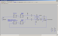
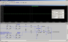
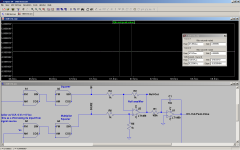
This is a functional simulation.
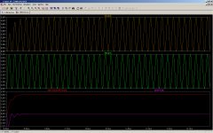
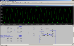
The signal source is squared by a multiplier. The signal source is feed to the input of a VCA and it's output is squared by a multiplier. The squared source and VCA are input to a differencing amplifier and the output of the difference amplifier feeds an integrator. The DC from the output of the integrator provides an error signal Vc for the VCA. When the squared source and squared output of the VCA are equal the output of the difference amplifier is null, 0Vdc average and the ripple component is in the low uV's. If the output of the VCA is less than the source the DC component at the output of the difference amp is negative and the integrator ramps up. if the output of the VCA is greater than the source the DC component at the output of the difference amp is positive and the integrator ramps down. The system locks the VCA output level to the amplitude of the source and the output of the integrator is a DC value equal to the peak of the source.
The speed of the system response is dependent on the response of the multipliers and the tau of the integrator. The output ripple is a function of the null and not a function of frequency. Therefore the integrator TC can be short. The LP effect of the integrator does help to minimized the ripple though.
The system is not sensitive to component tolerance and any error can be trimmed out.
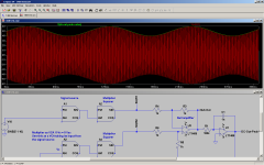
The last two plots show output ripple from the integrator. The second one for a longer integrator tau.
This is a functional simulation.
The signal source is squared by a multiplier. The signal source is feed to the input of a VCA and it's output is squared by a multiplier. The squared source and VCA are input to a differencing amplifier and the output of the difference amplifier feeds an integrator. The DC from the output of the integrator provides an error signal Vc for the VCA. When the squared source and squared output of the VCA are equal the output of the difference amplifier is null, 0Vdc average and the ripple component is in the low uV's. If the output of the VCA is less than the source the DC component at the output of the difference amp is negative and the integrator ramps up. if the output of the VCA is greater than the source the DC component at the output of the difference amp is positive and the integrator ramps down. The system locks the VCA output level to the amplitude of the source and the output of the integrator is a DC value equal to the peak of the source.
The speed of the system response is dependent on the response of the multipliers and the tau of the integrator. The output ripple is a function of the null and not a function of frequency. Therefore the integrator TC can be short. The LP effect of the integrator does help to minimized the ripple though.
The system is not sensitive to component tolerance and any error can be trimmed out.
The last two plots show output ripple from the integrator. The second one for a longer integrator tau.
Attachments
Last edited:
- Home
- Design & Build
- Equipment & Tools
- Low-distortion Audio-range Oscillator