Does anyone have a source for a good surface mount to DIP adapter? I'm having trouble finding one.
In stock at Newark. TE conectivity (Formerly Augat / Thomas & Betts) Gold flashed berylium copper 4 point contact per pin.
808-AG12SM 8 pin
814-AG12SM 14 pin
816-AG11SM 16 pin.
Pricey at ~$5.72 ea. but the best I know of.
http://www.aboveboardelectronics.com/thomasandbetts/pdf/au_sockets/surf_800sm.pdf Spec sheet
Doc
Last edited:
Thanks. I appreciate all the help.
Also check Sparksfun they have a range of adapters for around 3-4 dollars.
David.
I think I'm going the wrong direction here. My post covered Surface Mount PCB to DIP IC conversion.
Doc
I need to buy some 8 position SOIC to DIP adapters. I found a few in different places.
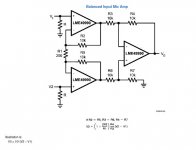
I have an idea for making a distortion analyzer. It's not an entirely new idea though. I'm still reading about different techniques for measuring distortion. My idea, which came to me out of the blue, is to use a differential amplifier with really high CMRR and extremely low distortion as a difference amplifier. The oscillator output goes to one input and the output from the device under test goes to the other input after going through an attenuator. The DUT has to be non-inverting for this to work, and the phase error has to be nill as well. Basically, if you feed a common mode signal to a differential amplifier, what's left at the output is the junk that's the difference.
The problem that I see with the typical notch filter type of distortion analyzer is that amplifiers under test don't just amplify and distort the fundamental frequency from the oscillator, they also amplifier and distort every harmonic that the oscillator produces, as well as the noise and IM products. So, the output of the DUT becomes a mess of harmonics, noise and IM products that you can't separate out with a notch filter.
Anyway, I'm still working with this idea and it's clear to me that in order for my device to work I need a very low distortion oscillator and a differential amp with crazy high CMRR and vanishingly low distortion. The LME49990 seems to fit the bill so far. CMRR is 137 dB and distortion is 0.00001%.
I need to buy some 8 position SOIC to DIP adapters. I found a few in different places.
I have an idea for making a distortion analyzer. It's not an entirely new idea though. I'm still reading about different techniques for measuring distortion. My idea, which came to me out of the blue, is to use a differential amplifier with really high CMRR and extremely low distortion as a difference amplifier. The oscillator output goes to one input and the output from the device under test goes to the other input after going through an attenuator. The DUT has to be non-inverting for this to work, and the phase error has to be nill as well. Basically, if you feed a common mode signal to a differential amplifier, what's left at the output is the junk that's the difference.
The problem that I see with the typical notch filter type of distortion analyzer is that amplifiers under test don't just amplify and distort the fundamental frequency from the oscillator, they also amplifier and distort every harmonic that the oscillator produces, as well as the noise and IM products. So, the output of the DUT becomes a mess of harmonics, noise and IM products that you can't separate out with a notch filter.
Anyway, I'm still working with this idea and it's clear to me that in order for my device to work I need a very low distortion oscillator and a differential amp with crazy high CMRR and vanishingly low distortion. The LME49990 seems to fit the bill so far. CMRR is 137 dB and distortion is 0.00001%.
Hi dirkwright,
Not just the distortion but the noise as well. Generally the noise becomes the limiting factor with the notch method. But if you whan to analyze an oscillator one has to use a notch filter. The null method depends on having a DUT in the loop.
It's good to have both in the shop.
David.
Yeah, I didn't think about how I was going to measure the distortion of the oscillator. I can't think of another way to do it right now without a notch filter.
Here's a more sophisticated one from this blog:
Active Twin-T filter
Here's his thread about this:
http://www.diyaudio.com/forums/equi...-twin-t-notch-filter-distortion-analysis.html
and here is the lazy man's design tool for twin T notch filters:
http://sim.okawa-denshi.jp/en/TwinTCRkeisan.htm
I think for testing this oscillator, we only need a few frequencies for the notch filter, not a continuous range. Something like 20, 200, 2K, and 20KHz would be fine.
Attachments
Last edited:
Here's a twin T filter with adjustable Q. Input on the left, output to the right.
If you haven't looked already. Check out Dick Moore's design of this filter.
Dick was good enough to lend me his TT will he's away from home.
he did an excellent job on it.
There a few things I would expand on it and I will comment on this later. But for i have to go to work.
David.
Hello,
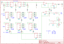
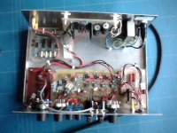
To measure distortion I used a circuit based on Ian Hickman's design from Electronics World magazine, issue August 1999. It uses a notch filter similar to the Robert Cordell THD Analyzer described in the Audio magazine, 1981. I designed a PCB just to learn the CAD program VUTRAX and didn't do that good a job. I used various parts that I had lying around and added an input attenuator built from scrap and also an RMS to DC board made using a dalo pen about 30 years ago. The frequency ranges are limited to three, 100 Hz to 250 Hz, 1k to 2.5 kHz, 10 k to 25 kHz. It is a little touchy to tune but it was good enough to measure 0.004 % distortion and noise at 1 kHz on the Oscillator test circuit that I made.
I have attached a picture of the Distortion Measuring unit.
Attachments
Hello,
To measure distortion I used a circuit based on Ian Hickman's design from Electronics World magazine, issue August 1999. It uses a notch filter similar to the Robert Cordell THD Analyzer described in the Audio magazine, 1981. I designed a PCB just to learn the CAD program VUTRAX and didn't do that good a job. I used various parts that I had lying around and added an input attenuator built from scrap and also an RMS to DC board made using a dalo pen about 30 years ago. The frequency ranges are limited to three, 100 Hz to 250 Hz, 1k to 2.5 kHz, 10 k to 25 kHz. It is a little touchy to tune but it was good enough to measure 0.004 % distortion and noise at 1 kHz on the Oscillator test circuit that I made.
I have attached a picture of the Distortion Measuring unit.
Nice job!
Thanks for the comments on the Distortion Analyzer. I have ordered parts for my Oscillator design. Farnell have mainly delivered with some shortages and I am waiting for some components from Digi-Key. I have almost finished the PCB layout but want the bits to check the footprints before completion. If the Oscillator goes well and if my enthusiasm is still high I will sort out the Distortion Analyzer and do a proper design and PCB layout. I have played around with auto fine tuning the notch which is necessary as the Oscillator and Notch frequencies aren't absolutely stable and have some ideas to try.
Anyone have a source for really low tolerance capacitors? I can barely find any +/-1%. I looked into getting an LCR bridge to match my own, but heck those things are killer expensive now. I can't believe I used to have a GR 1650 bridge that was perfectly fine but sells for something like $800 now!?!?! Even that bridge was only good for +/-1%. I seriously doubt that the capacitance measuring feature on my DMM is worth a crap.
although crappy meters are not good for measuring values, even a crappy cap meter is usually great for matching parts ... if that's all you're asking of it.
i bought a pic-based diy meter several years ago that is quite accurate (as measured against calibrated expensive HP analyzers i used to have access to at a past employer) as well as great for matching. i'm not home so i'll post the details later. i think it was by Almost All Digital or something like that. For about $100. i think it was a great deal ...
mlloyd1
edit:
ok, i took a guess and found the link: L/C Meter II, a digital inductance meter / capacitance meter.
Last edited:
I don't have a good source. The best that I know of is Farnell who supply up to 10 nF polystyrene capacitors LCR Components FSCEX series with a 1 % tolerance. Larger values seem to be limited to 3 % tolerance Polypropylene film up to 2.4uF Panasonic ECWF series from Digi-Key.
I am interested if anyone can suggest a better source.
I am interested if anyone can suggest a better source.
IMHO using 1% polystirene capacitors or ultra-low THD opamp in the shown APF generator is quite an overkill unless you're not going to substantially improve the ALC loop, which is * definitely * the main source of THD (and poor sideband performance). I think you can go for the ubiquitous 5% red WIMA polypropylene caps (FKP), which are pretty good indeed for this kind of job.
L.
L.
Out of the the available caps Wima, Panasonic etc. How many 5% caps would one need to by to match to 1% or better? How many 20%?
If it matters, isn't it the RC combo that needs to be matched between sections, HP-LP that make up the a BP function? If this is true and it is for some oscillator types then the sections can be trimmed with the R to match.
David.
If it matters, isn't it the RC combo that needs to be matched between sections, HP-LP that make up the a BP function? If this is true and it is for some oscillator types then the sections can be trimmed with the R to match.
David.
- Home
- Design & Build
- Equipment & Tools
- Low-distortion Audio-range Oscillator