Gentle beings ------ 2H is from dielectric and 3H is from connection... lead to plate interfacing.
3H variations are often used to determine QC/QA in manufacturing. A higher than normal 3H often leads to a less reliable part over time.
Audible distortions are results from DA. Only noticed with asymet test signals (not THD/IM tests). It's level is voltage, time and circuit Z dependant.
THx-RNMarsh
Last edited:
Ebay oscillator
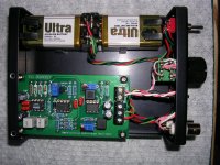
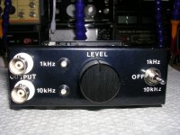
I got a couple of the ebay low distortion 1kHz oscillators mentioned earlier in this thread and pimped them up a little. I replaced the NE5532s with LME49720s, the TL072 with an OPA134, the frequency determining caps C1 & C2 with 1% polypropylenes, and the integrator caps C3 & C4 with polyphenylene sulphides. I tried varying the output level with a pot on the -ve supply to the current reference resistor R12 but this was only partially successful - the oscillations stopped when the output level was reduced by much more than about half. Instead I increased the output resistor R14 from 100R to 1k and connected this to a 1k pot for varying the output level. Normally I would have followed this with a buffer amp to provide constant (low) output impedance but I didn't have enough space in the enclosure that I was using. In any event this method works fine for my purposes. I discovered that the oscillator provides a low distortion 10kHz sinewave by the simple expedient of changing C1 & C2 from 47n to 4.7n. So I made a 1kHz plus a 10kHz oscillator and put them in a small aluminium enclosure along with batteries, leds, a potentiometer, a switch, and connectors. The power switch is centre off whilst the other positions power one or other of the oscillator boards. One or other of the leds light up to indicate which board is powered. Photos below.
I got a couple of the ebay low distortion 1kHz oscillators mentioned earlier in this thread and pimped them up a little. I replaced the NE5532s with LME49720s, the TL072 with an OPA134, the frequency determining caps C1 & C2 with 1% polypropylenes, and the integrator caps C3 & C4 with polyphenylene sulphides. I tried varying the output level with a pot on the -ve supply to the current reference resistor R12 but this was only partially successful - the oscillations stopped when the output level was reduced by much more than about half. Instead I increased the output resistor R14 from 100R to 1k and connected this to a 1k pot for varying the output level. Normally I would have followed this with a buffer amp to provide constant (low) output impedance but I didn't have enough space in the enclosure that I was using. In any event this method works fine for my purposes. I discovered that the oscillator provides a low distortion 10kHz sinewave by the simple expedient of changing C1 & C2 from 47n to 4.7n. So I made a 1kHz plus a 10kHz oscillator and put them in a small aluminium enclosure along with batteries, leds, a potentiometer, a switch, and connectors. The power switch is centre off whilst the other positions power one or other of the oscillator boards. One or other of the leds light up to indicate which board is powered. Photos below.
Attachments
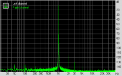
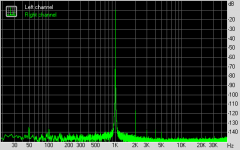
The distortion is more than 100dB down at both 1kHz and 10kHz. I'll need a better spectrum analyser to characterise it better than that. Unfortunately I didn't measure the distortion of the original so I don't know how much the tweaks improved things. Not by a huge amount I suspect. As you say some tweaking around the fet will probably improve things even further. Given that its a state variable oscillator I might also try a simple multiphase rectifier to reduce the ripple at the fet gate. Another idea I've toyed with is designing an oscillator with a four op-amp state variable loop - carefully done that should reduce the distortion to immeasurability - anyone tried it? I'm about halfway through building a variable frequency version of the oscillator using a 2 pole 24-way switch to provide a close packed range of switched frequencies, rather than continuously variable frequency with a double ganged pot and all the problems that entails.
These modules cost about £10 A&T, or £3-4 as a bare pcb, from ebay UK. I think that's pretty good value given their excellent performance and tweakability. The pcbs are pretty robust too; I desoldered and resoldered one of the resistors four times with no sign of damage to the pads, plating through, or the pcb itself.
These modules cost about £10 A&T, or £3-4 as a bare pcb, from ebay UK. I think that's pretty good value given their excellent performance and tweakability. The pcbs are pretty robust too; I desoldered and resoldered one of the resistors four times with no sign of damage to the pads, plating through, or the pcb itself.
I also played with this oscillator a while ago, you may like to have a look at my initial results:
http://www.diyaudio.com/forums/equi...n-audio-range-oscillator-553-post4909629.html
I hope to be able to resume this project in the near future. I'm still interested in this oscillator, and being now better equipped for the measurements (variable-frequency notch filter, 60dB post-amp, improved audio interface), there is achance to better assess its performance.
Regards,
Braca
Hi Braca. As I remember it was reading your post that inspired me to experiment with this oscillator. Did you ever measure the distortion of an unmodified oscillator? As you will have seen I tried your suggestion for output level control but it didn't give me anything like full range before the oscillator stopped. Did you do better than me? I must say again I find this oscillator amazing value for money.
Regards, David
Regards, David
Hello, David.
Sorry to have forgotten previous interaction.
Yes, I measured the distortion in the as-is state, but also after having replaced the 5532's with 4562, and TL072 with 134A.
I used the RMAA software at the time and wasn't happy with its flexibility and the lack of control over what I do with it. But FWIW, I'm enclosing the three spectra - at least they show the reduction of the harmonics after the two changes I made.
Regards,
Braca
Attachments

thanks.
This is going to be my second test with the RTX6001 (after loopback).
Hopefully it is going to be easy to set up to see the existing performance of my low distortion oscillator.
Then I will look at my two LNA, +60dB Wurcer and +80dB Frex.
If I can get loopback, osc and LNA all giving sensible results, I might be ready to look at amplifier performance.
somewhere in the previous 700 pages i posed a 4 phase level detector using an LM339 and no diodes. It works pretty well. Not as well as a sample and hold/track and hold or Davida's ADC/multiplying DAC trick.
You will need to change the integrator cap with frequency so that would be another wafer on the switch.
You will need to change the integrator cap with frequency so that would be another wafer on the switch.
somewhere in the previous 700 pages i posed a 4 phase level detector using an LM339 and no diodes. It works pretty well. Not as well as a sample and hold/track and hold or Davida's ADC/multiplying DAC trick.
You will need to change the integrator cap with frequency so that would be another wafer on the switch.
It's here: Demian's original post with his LM339 detector
I have assembled the sine generator and there are problems with the signal spectrum. What for excitation of a sine curve?Hi to everyone.
I am author of this generator:

Victor

Last edited:
- Home
- Design & Build
- Equipment & Tools
- Low-distortion Audio-range Oscillator