If you have no experience at all in low THD generators I would suggest you to begin with the simplest one, just to experiment a bit and see what kind of problems you have to face to build and * measure * it - for reference, the full schematics of my clone is in post #255.
Ciao,
L.
Ciao,
L.
If you have no experience at all in low THD generators I would suggest you to begin with the simplest one, just to experiment a bit and see what kind of problems you have to face to build and * measure * it - for reference, the full schematics of my clone is in post #255.
Ciao,
L.
OK, I must have missed your schematic, obviously. Thanks for sharing.
What's the 1kohm trimmer near U1 for? and the other one by U6?
Is the low input bias of a jeft opamp like the OPA2134 critical to the performance of your oscillator? If not, then there are lower noise opamps out there that could be used instead.
Last edited:
I'm not an expert, but I would say that if an oscillator was better than 1ppm THD with noise @ -130dB or so, over the range of 10Hz to 100kHz, then that would be a pretty good oscillator.
then you're done already - just buy a DAC:
ES9018 SABRE32 Reference 32-bit 8-Channel Audio DAC
DNR (dB) 135 (mono) 133 (stereo) 129 (8ch)
THD (dB) -120
then you're done already - just buy a DAC:
ES9018 SABRE32 Reference 32-bit 8-Channel Audio DAC
DNR (dB) 135 (mono) 133 (stereo) 129 (8ch)
THD (dB) -120
Well, as I said, I'm no expert. Maybe these oscillators we are considering are better than that? I don't know.
Any experts on SG505's here on this truly exiting thread?
Both my colleage and I recently purchased one of these and we already tried a few things to improve the residual harmonics but to no avail. I don't exactly find the SG505 easy to understand in all details (AGC section, notably) but I don't claim to be an expert. Both units are still fully within spec (as verified on the AP2722), so it's really about tuning the "last bit out of them".
So, anybody have a hint to known SG505 tricks (except for getting the hum down which is managable)? Not that I would expect the Tek guys didn't try tweak the hell out of it at their time, but after so many years there might be a chance that someone found ways to improve it with moderate effort.
So you do have your own oscillator up and running.
Of course--I'd not comment at this detail if I didn't had the background.
If you have no experience at all in low THD generators I would suggest you to begin with the simplest one, just to experiment a bit and see what kind of problems you have to face to build and * measure * it.
Definitely. Building low distortion oscillators is a steep learning curve!
The schematic is only half the rent--bad layout can completely ruin performance.
What's the 1 kOhm trimmer near U1 for? And the other one by U6?
The former pre-trims the Q of the oscillator such that J1 is working with just as much voltage across it as necessary. The latter adjusts the symmetry of the rectifier to minimize ripple.
Then you're done already - just buy a DAC:
ES9018 SABRE32 Reference 32-bit 8-Channel Audio DAC
DNR (dB) 135 (mono) 133 (stereo) 129 (8ch)
THD (dB) -120
An ES9018 will not have -130 dB dynamic range at full scale. This figure is measured at -60 dBFS and degrades above ~35 dBFS. Also it would surely not give 1 ppm distortion at 100 kHz!
Maybe these oscillators we are considering are better than that? I don't know.
A reasonable and realistic design goal for a very good DIY oscillator is perhaps:
* Frequency range 10 Hz to 100 kHz, in 4 decades
* Amplitude range -60 dBu to +20 dBu
* Harmonics below -125 dB for 20 Hz-20 kHz
* Harmonics below -110 dB for 10 Hz-40 kHz
* Harmonics below -100 dB for 10 Hz-100 kHz
* THD+N (20 kHz BW) below 110 dB for 20 Hz-20 kHz
* THD+N (80 kHz BW) below 100 dB for 10 Hz-40 kHz
* THD+N (500 kHz BW) below 90 dB for 10 Hz-100 kHz
* Settling below 1 s for 100 Hz-100 kHz
* Settling below 5 s for 10 Hz-100 kHz
* Amplitude flatness below 0.1 dB for 10 Hz-20 kHz (ref. 1 kHz)
* Amplitude flatness below 0.5 dB for 10 Hz-100 kHz (ref. 1 kHz)
Samuel
Hello Bob,HI PChi,
As a point of reference, the oscillator I have in my THD analyzer from 1981 settles to 0.1dB at 20Hz within 1 second and to within 0.01 or so within 3 seconds. This is for either decade changes or frequency changes within a range. Total analyzer THD at 20Hz is less than 0.006%, but I think most of that is in the analyzer side and that the oscillator is much better than that.
The SV oscillator uses a simple full-wave agc detector, but uses speed-up diodes across most of the integrator input resistance. Also, the agc detector capacitors are switched for the decade range and are all precharged by each other to the nominal operating value from whatever range was previously in use. Both of these techniques speed up settling when frequency or range is changed.
The design is shown in the THD analyzer article on my website at CordellAudio.com - Home.
Cheers,
Bob
Thanks for the website. Sorry for the dely in replying. I am back in work so cash rich but time poor. I remember trying to get a copy of Audio here in the UK for your article without success.
My design goals were:-
To learn KiCAD.
Continuous tuning (in ranges)
All mounted on a PCB for consistency.
I wasn't bothered about settling time.
I used a Phase Shift Circuit to minimise gain changes with frequency adjustment using unmatched dual ganged potentiometers. But this increases distortion with the high operational amplifier common mode signal.
Sample and hold because I have had problems with loop stability in the past.
High signal level for low noise but reduced linearity.
If I designed another I would consider using an analog multiplexer with close tolerance surface mount resistors which are quite reasonably priced. Multipling DACs don't seem that linear.
Lest see some more design ideas realised with test results.
It's going to be hard to compete with AP because it's their job and they will have spent many hours which the amatuer can't do.
Definitely. Building low distortion oscillators is a steep learning curve!
(...)
The schematic is only half the rent--bad layout can completely ruin performance.
(...)
The former pre-trims the Q of the oscillator such that J1 is working with just as much voltage across it as necessary. The latter adjusts the symmetry of the rectifier to minimize ripple.
(...)
A reasonable and realistic design goal for a very good DIY oscillator is perhaps:
* Frequency range 10 Hz to 100 kHz, in 4 decades
* Amplitude range -60 dBu to +20 dBu
* Harmonics below -125 dB for 20 Hz-20 kHz
* Harmonics below -110 dB for 10 Hz-40 kHz
* Harmonics below -100 dB for 10 Hz-100 kHz
* THD+N (20 kHz BW) below 110 dB for 20 Hz-20 kHz
* THD+N (80 kHz BW) below 100 dB for 10 Hz-40 kHz
* THD+N (500 kHz BW) below 90 dB for 10 Hz-100 kHz
* Settling below 1 s for 100 Hz-100 kHz
* Settling below 5 s for 10 Hz-100 kHz
* Amplitude flatness below 0.1 dB for 10 Hz-20 kHz (ref. 1 kHz)
* Amplitude flatness below 0.5 dB for 10 Hz-100 kHz (ref. 1 kHz)
Could't agree more
")
As far as the opamp is concerned: you need both high speed and high GBW to keep THD low at high frequencies, high input impedance, very low noise current density - in this particular application an OPA2134 performs definitely better (at low to mid freqs, at least) than, say, a LME49710, although this one has 1/3 the noise voltage density of the former. The original 239A employed an HA-2625, which is unfortunately classified either as obsolete or retired by Intersil - it was a bipolar uncompensated opamp featuring high speed (100 MHz GBW, > 60 dB OLG @ 100 kHz, SR 35 V/usec), high input impedance (300 Mohm), low noise current density (0.16 pA/sqrt(Hz)): these are not-so-common specs even in modern opamps, unless you are going to choose expensive beasts like the OPA637 - all in all, OPA2134 is a good starting point...
L.
I have a similar solution that is mostly discrete if you prefer. It would be cheaper as well.
Hi Demian,
I'm interested in looking at everything. If it's not too much trouble can you post it?
Last edited:
Could't agree more
The original 239A employed an HA-2625, which is unfortunately classified either as obsolete or retired by Intersil - it was a bipolar uncompensated opamp featuring high speed (100 MHz GBW, > 60 dB OLG @ 100 kHz, SR 35 V/usec), high input impedance (300 Mohm), low noise current density (0.16 pA/sqrt(Hz)): these are not-so-common specs even in modern opamps, unless you are going to choose expensive beasts like the OPA637 - all in all, OPA2134 is a good starting point...
L.
I have 10 of these in the plastic DIP package if anyone is interested.
I have 10 of these in the plastic DIP package if anyone is interested.
HA-2625? Lucky man! I would be interested in a couple of them
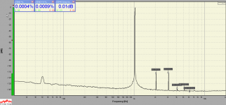
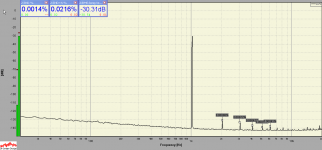
This is the 239A clone working at 20 Vpp out into 10 kohm - measured THD is almost only the THD of the EMU 0204 itself. A plot of the FET operating Vds (~88 mVpp) is attached too.
Ciao,
L.
Attachments
Last edited:
My 339A/239A clone uses an LT1468 for the main amp -- works quite well, considering it has a 10:1 cap ratio instead of HP's 100:1 ratio. I call this version the IG-339B -- it's built into a Heath IG-18 chassis and uses the Heath tuning resistor switches. The Heath mylar caps however have been changed to polypropylenes.
The fundamental is 1kHz at 6.3VRMS, level-adjusted by a 10k pot to 1VRMS and fed into my Active Twin-T filter to reduce the fundamental by 60dB without attenuating harmonics at all. The ADC is an E-MU 0204.
The fundamental is 1kHz at 6.3VRMS, level-adjusted by a 10k pot to 1VRMS and fed into my Active Twin-T filter to reduce the fundamental by 60dB without attenuating harmonics at all. The ADC is an E-MU 0204.
Attachments
Well, I'm certainly willing to get a PCB together and order it. I use Pad2Pad. Surface mount or through hole devices?
Reed relays ok for switching? 5V? I'm having some trouble figuring out the switching arrangement for the frequency setting resistors and capacitors. Anyone have a plan?
Reed relays ok for switching? 5V? I'm having some trouble figuring out the switching arrangement for the frequency setting resistors and capacitors. Anyone have a plan?
Everything you need is on Dick's web page.
http://www.moorepage.net/RC.html
HA-2625? Lucky man! I would be interested in a couple of them
This is the 239A clone working at 20 Vpp out into 10 kohm - measured THD is almost only the THD of the EMU 0204 itself. A plot of the FET operating Vds (~88 mVpp) is attached too.
Ciao,
L.
Just PM with an address.
Any experts on SG505's here on this truly exiting thread?
Both my colleage and I recently purchased one of these and we already tried a few things to improve the residual harmonics but to no avail. I don't exactly find the SG505 easy to understand in all details (AGC section, notably) but I don't claim to be an expert. Both units are still fully within spec (as verified on the AP2722), so it's really about tuning the "last bit out of them".
So, anybody have a hint to known SG505 tricks (except for getting the hum down which is managable)? Not that I would expect the Tek guys didn't try tweak the hell out of it at their time, but after so many years there might be a chance that someone found ways to improve it with moderate effort.
Bruce Hofer did (as usual) an excellent job here. There are a lot of subtleties going on (and I'm sur I'm missing one or the other), and it is unlikely that we'll find an easy fix which will significantly improve performance. Just to highlight a few details:
* It looks like residual ripple of the peak level detector is cancelled through C1502 and C1603;
* The NE5534s implement various tricks--feed forward compensation (C1514, C1622), two-pole compensation (C1405, C1406, R1405), forced class A operation (R1621) and even a simple composite opamp (Q1620, see US-patent 4296381);
* The for higher frequency ranges unused integrator caps in the second integrator (C1312, C1320, C1322) are precharged to a specific voltage through R1421/R1422. I presume this speeds up settling after a range switch, because the capacitors are already in the correct phase relation to those in the first integrator (which a precharged to 0 V);
* The power supply of the peak detector is heavily low-pass filtered (R1611, C1600). This localises the current loop of the distorted currents, and avoids coupling to the main signal path.
One thing you could try is to make the drain feedback of Q1501 adjustable. Unsolder the ends of R1510/R1513 which connect to the gate of Q1501; take a (quality multi-turn) 1k trim pot; connect its wiper to the gate of Q1501 and the resistance element ends to R1510 and R1513 respectively. By adjusting the trimmer you might be able to reduce the 2nd harmonic for certain frequencies. But make sure it doesn't get worse for others!
Something else might be the addition of a 68r resistor between pin 5 and 6 of U1401 (as done for U1520). This forces the output stage of the NE5534 into class A operation, with possibly some distortion improvement.
OK, then I just do this for me and this isn't going to become something for everyone. We're back to punting ideas around, like always.
His page is great for theory, thanks.
- Home
- Design & Build
- Equipment & Tools
- Low-distortion Audio-range Oscillator