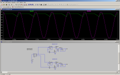
Here's an equation which describes the VTL LDR behavior --r2 is very high as the errors of a few percent are offsetting. I plugged the datasheet from the VTL5C9 into Eureqa and went to the deli for a sandwich:
An externally hosted image should be here but it was not working when we last tested it.
The lines are quite compressed at the low R end, so the errors exceed 10% as the current approaches 40mA.
Edit == Yes, there are too many parens!
Thanks for this jackinnj,
I can't operate my calculator after working all night installing a fiber node hanging on the strand on a pole. I can barely type.
Is there a formula that includes the time constants? That would be needed for modelling.
CdS can be turned on rapidly but are rather passive and slower on the turn off which make them difficult to use in a full range oscillator at higher frequency.
David.
I've been to Mr. Moore's pages before and I can't find a schematic for his wide range oscillator. I can layout a PCB board myself.
He used Cordell's schematic with a few minor changes as listed in his article.
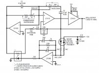
Cordell's schematic is on his site here. http://www.cordellaudio.com/papers/thd_analyzer.pdf
He used Cordell's schematic with a few minor changes as listed in his article.
Cordell's schematic is on his site here. http://www.cordellaudio.com/papers/thd_analyzer.pdf
Hmmm, unless something has changed since the article was written, the best performance of the oscillator (which I guess is the residual on page 60 of Part 3) is 0.003% or thereabouts, depending on frequency, range and output level.
The LT Wein bridge circuit claims the same number.
So, are people seeing much better numbers out of the Cordell oscillator than the article presents?
Dick has the distortion down a couple of magnitudes lower now. If you look around his site you will find the latest improvements. The noise and residual in earlier mods was about 0.0003%.
I'll see if I can find likes to this.
http://www.moorepage.net/IG-18-2.html
If you look at the bottom of the page the last spectrum display is 0.00063% THD+N and 0.00058% THD @ 10Vrms out to 10KHz.
This is very good. Of course the disto will go down at lower level but with the cost of lower SNR.
David.
Last edited:
Is there a formula that includes the time constants? That would be needed for modelling.
Beyond my pay grade...but one of my sons could do it.
Track and Hold
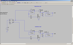
This is a very simple track and hold circuit I developed.
There are to variations shown here. The first is a single phase reset and the second
is a quadrature reset. The quadrature reset version having a longer hold time.
A1 generates the signals for the simulation and is replaced by an oscillator in a real world circuit.
The circuit offers some improvement over conventional track and hold
systems. There is an absents of glitch and ringing associated with fast switching circuits.
All of the signals are supplied from the input signal for the rectification and reset.
No pulse shaping circuits are required.
This TH could be used to replace the conventional peak detector circuit found in oscillator AGC's
The output power is far greater than that of a conventional peak detector and will decrease settling time of an oscillator.
The circuit illustrated uses a transistor as a very low leakage diode. The output buffer op amp should be a Jfet input type
because of their low input bias and leakage currents. The input buffer op amp is not critical provided it cover the desired bandwidth.
The arrangement with out feed back around the rectifier offers better performance at higher frequencies and doesn't suffer as much overshoot
in the absence of resistive loading. R1 or R3 set the reset current. Higher values of resistance reduce the reset pull down.
Like any conventional diode rectifier there is some peaking in the output from the peak of the sine.
The circuit tracks and holds on the positive of the sine and resets on the negative swing.
For a negative version simply replace the transistors with PNP type.
This could be used as a drop in replacement for the peak detector in Bob Cordell's oscillator circuit and others.
Cheers,
David.
Attachments
Last edited:
Dick has the distortion down a couple of magnitudes lower now. If you look around his site you will find the latest improvements. The noise and residual in earlier mods was about 0.0003%.
I'll see if I can find likes to this.
IG-18 #2, the BIG-18
If you look at the bottom of the page the last spectrum display is 0.00063% THD+N and 0.00058% THD @ 10Vrms out to 10KHz.
This is very good. Of course the disto will go down at lower level but with the cost of lower SNR.
David.
I'm sorry but I miss-wrote earlier. All these darn zeros! OK, the LT Wein bridge oscillator is claimed to have 0.0003% THD. I know everyone seems to think it's not very good but if they really measured the thing then who's to say they are wrong?
Also, LT has another circuit with an RMS -> DC converter in the AGC:
http://cds.linear.com/docs/LT Journal/05_03-12-LTC1968-Pei.pdf
What I find interesting is that he measured it at 0.0025% THD @ 100kHz. He doesn't mention anything about a lower frequency.
Maybe if I combine the features of this oscillator with the other bridge oscillator, I might have something good?
Attachments
Hi Dirkwright,
Thanks for bringing this link to my attention; I had been unaware if it. It looks like Glen has done a very nice job of updating my THD analyzer from 1981, using modern parts and using relays to replace those damned rotary switches I had in mine. I have often thought of updating mine by using relays for frequency selection as well. It does take a good number of them, epecially if you cover 11 spot frequencies per decade, but it is worth it, especially in terms of assembly labor. I don't think that Glen provided a link to my article. It can be found at CordellAudio.com - Home under the instrumentation tab.
Cheers,
Bob
Hi Bob, your website is a gold mine of good information. Thank you for providing it. I really enjoy your power amplifier book too.
If and when I do build something, I will take your suggestions into consideration. Thanks for your comments!
This is a very simple track and hold circuit I developed.
There are to variations shown here. The first is a single phase reset and the second
is a quadrature reset. The quadrature reset version having a longer hold time.
A1 generates the signals for the simulation and is replaced by an oscillator in a real world circuit.
The circuit offers some improvement over conventional track and hold
systems. There is an absents of glitch and ringing associated with fast switching circuits.
All of the signals are supplied from the input signal for the rectification and reset.
No pulse shaping circuits are required.
This TH could be used to replace the conventional peak detector circuit found in oscillator AGC's
The output power is far greater than that of a conventional peak detector and will decrease settling time of an oscillator.
The circuit illustrated uses a transistor as a very low leakage diode. The output buffer op amp should be a Jfet input type
because of their low input bias and leakage currents. The input buffer op amp is not critical provided it cover the desired bandwidth.
The arrangement with out feed back around the rectifier offers better performance at higher frequencies and doesn't suffer as much overshoot
in the absence of resistive loading. R1 or R3 set the reset current. Higher values of resistance reduce the reset pull down.
Like any conventional diode rectifier there is some peaking in the output from the peak of the sine.
The circuit tracks and holds on the positive of the sine and resets on the negative swing.
For a negative version simply replace the transistors with PNP type.
This could be used as a drop in replacement for the peak detector in Bob Cordell's oscillator circuit and others.
Cheers,
David.
Very interesting, thank you.
I know everyone seems to think it's not very good but if they really measured the thing then who's to say they are wrong?
0.0003% isn't a bad figure at all, but an SVF ring can do better - even a bridged-t can be as simple as a wien bridge and still perform way better. Have a look a the HP 239A schematics - my 239A clone sits at about 0.00005% @ 20 Vpp out, 1kHz.
L.
0.0003% isn't a bad figure at all, but an SVF ring can do better - even a bridged-t can be as simple as a wien bridge and still perform way better. Have a look a the HP 239A schematics - my 239A clone sits at about 0.00005% @ 20 Vpp out, 1kHz.
L.
OK, thanks. I can't find a free HP 239A schematic. I have to pay for one.
")
Thanks. I see that it is a bridged T feedback type of oscillator. I am not familiar with those yet.
Unfortunately, figure 8-3 is blurry and I can't read it. It shows a simplified ACC.
This looks very easy to build. Thanks again!
Last edited:
Thanks. I see that it is a bridged T feedback type of oscillator. I am not familiar with those yet.
A bridged T is a transform of the Wien Bridge just as simple.
David.
Unfortunately, figure 8-3 is blurry and I can't read it. It shows a simplified ACC.
Have to check, but if I remember well I have a slightly more readable version of that - I'll let you know.
L.
A bridged T is a transform of the Wien Bridge just as simple.
David.
Thanks. Perhaps I can use the LTC1968 RMS->DC converter circuit shown in the LT app note for the AGC in a bridged T oscillator? The LTC1968 is supposed to be very accurate over the audio frequency span. The amplifier could be something really linear like an LME49710 (maybe plus a buffer in case the feedback network has low impedance). I assume that the RC components in the bridge T feedback network have to be matched, so using a pot to vary frequency would probably not be a good idea, which I guess is why the HP239A uses switched parts.
AD637 would be a better choice for DIY since it's available in DIP package.
Last edited:
Thanks. Perhaps I can use the LTC1968 RMS->DC converter circuit shown in the LT app note for the AGC in a bridged T oscillator? The LTC1968 is supposed to be very accurate over the audio frequency span. The amplifier could be something really linear like an LME49710 (maybe plus a buffer in case the feedback network has low impedance). I assume that the RC components in the bridge T feedback network have to be matched, so using a pot to vary frequency would probably not be a good idea, which I guess is why the HP239A uses switched parts.
AD637 would be a better choice for DIY since it's available in DIP package.
The LTC1968 requires a lot of output filtering to get the ripple down. Consequently the TC is to long for fast settling at frequencies above a few KHz in a variable oscillator.
Other than they are great.
David.
Hmmm, unless something has changed since the article was written, the best performance of the oscillator (which I guess is the residual on page 60 of Part 3) is 0.003% or thereabouts, depending on frequency, range and output level.
The LT Wein bridge circuit claims the same number.
So, are people seeing much better numbers out of the Cordell oscillator than the article presents?
Hi dirkwright,
I think you are off by a factor of 10. The total analyzer residual is about 0.0003% at 1 kHz, and below 0.001% at 20kHz.
The oscillator by itself is quite a bit better than that.
I did a little tweaking about a year ago (after 30 years I figured it needed some TLC), looking more closely for where the limiting issues were on the residual. Of course, the challenge in doing that is to isolate whether the residual distortion is coming from the oscillator or the analyzer (the latter being more complex and having a more difficult job, especially in regard to its need to very strongly reject the fundamental, which can form part of the residual).
I had to go to significant lengths to measure the oscillator distortion alone, such as extremely precise active twin-T feeding into an HP3580A spectrum analyzer. I don't remember the number, but the oscillator THD was way down there, especially at easy frequencies like 1kHz.
Residual in the analyzer section is what dominates the end-to-end analyzer performance. Getting an extremely deep auto-null at extremely low levels of distortion is difficult, as the synchronous detectors have little fundamental to work with, somewhat buried in noise, under those conditions. Also, any phase noise hurts the null as well. So, when the analyzer is reading down around 0.0003%, a decent portion of that residual is left-over fundamental.
The most significant improvement that I made was to put in trimmers to adjust the distortion-reducing feedback to the JFET gates, as in the original design the ratio was set at the nominal 50% value. In the real world, you can get some more improvement by makng it tweakable.
My analyzer was published in 1981. That may have actually been before the AP1 came out. My state variable oscillator was inspired by an AES paper given by Bruce Hofer, then of Tektronix - his paper was essentially referring the the SV that went into the SG505. Once I did the oscillator, it was clear how to make the necessary notch filter out of the same topology, and I already knew how to do auto-tune based on lots of IC PLL work I did at Bell Labs. The log-linear VCAs I used for auto-scaling the distortion readings came out of earlier work I had done for VCAs used in a 4-channel preamp I did in the '70s (remember Quad?).
Bruce Hofer and Rich Cabot have been good friends of mine since their Tek days, and I remember on a business trip to Oregon stopping by to see Rich, where he showed me the beginnings of the AP1 hooked up to what I think was a very early-generation PC. They are two of the best engineers I have ever met.
Cheers,
Bob
This is a very simple track and hold circuit I developed.
There are to variations shown here. The first is a single phase reset and the second
is a quadrature reset. The quadrature reset version having a longer hold time.
A1 generates the signals for the simulation and is replaced by an oscillator in a real world circuit.
The circuit offers some improvement over conventional track and hold
systems. There is an absents of glitch and ringing associated with fast switching circuits.
All of the signals are supplied from the input signal for the rectification and reset.
No pulse shaping circuits are required.
This TH could be used to replace the conventional peak detector circuit found in oscillator AGC's
The output power is far greater than that of a conventional peak detector and will decrease settling time of an oscillator.
The circuit illustrated uses a transistor as a very low leakage diode. The output buffer op amp should be a Jfet input type
because of their low input bias and leakage currents. The input buffer op amp is not critical provided it cover the desired bandwidth.
The arrangement with out feed back around the rectifier offers better performance at higher frequencies and doesn't suffer as much overshoot
in the absence of resistive loading. R1 or R3 set the reset current. Higher values of resistance reduce the reset pull down.
Like any conventional diode rectifier there is some peaking in the output from the peak of the sine.
The circuit tracks and holds on the positive of the sine and resets on the negative swing.
For a negative version simply replace the transistors with PNP type.
This could be used as a drop in replacement for the peak detector in Bob Cordell's oscillator circuit and others.
Cheers,
David.
Hi DB,
This is a nice circuit, and may prove very worthwhile.
The full-wave detector in my oscillator is not a true peak detector because it has a significant 10k resistor between the FW rectifier output (from two open-emitters) and the agc filtering capacitors. This seems to work better than a true peak detector in this position.
Although I always worried a lot about the agc ripple, it does not appear to be the limiting issue in distortion in my oscillator, but rather the small distortion of the JFET in the agc. There is a noise/distortion tradeoff there. The fact that agc is not a big problem for me is partly due to the fact that that the agc filter capacitance is range-selected and that anti-parallel diodes greatly reduce the agc feedback amplitude once the oscillator has settled.
Another approach is available for reduced agc jitter, and this is a result of the beauty of the SV providing in-phase and quadrature outputs. Instead of just using a full-wave rectifier (two phases), one can use a 4-phase detector by connecting FWRs to the quadrature output as well (as long as level differences between the quadrature and in-phase outputs are close to being the same). If one wanted to go to a real extreme, they could go to 8 phase detection by combining quadrature and in-phase outputs to form yet another set of detector signals.
Cheers,
Bob
Hi Bob, your website is a gold mine of good information. Thank you for providing it. I really enjoy your power amplifier book too.
If and when I do build something, I will take your suggestions into consideration. Thanks for your comments!
Hi Dirkwright,
Thank you for your very kind words. Look for some new info on the website very soon. As you may know, I published an article in Linear Audio this month describing my VinylTrak MM/MC phono preamplifier. There is a bunch of supplemental information on the design that will go up on my website shortly.
In the meantime, if you love audio I very strongly suggest you subscribe to Jan Didden's wonderful Linear Audio publication, out every 6 months. It just hit the 200-page mark. Check it out at www.linearaudio.net - home. Jan and I will both be at RMAF in Denver, a great audio show. Jan will have an exhibit table there.
Cheers,
Bob
- Home
- Design & Build
- Equipment & Tools
- Low-distortion Audio-range Oscillator