In the long-ago past, I've owned one or two osillators that used bulbs for the oscillator agc. One was an EICO 377. When in college, I built a switched-frequency bridged-T oscillator using a thermistor for the agc element. It worked fine, but back then I did not have really good instrumentation for measuring THD.
After I graduated with my BS, I leaned of JFETs and their use as voltage-controlled resistors. Shortly thereafter I discovered how HP used a distortion-reduction approach with JFETs as the AGC element in their oscillators (they fed back half the signal at the drain to the gate). Since then I've only built oscillators with JFETs.
However, I do wonder if the old Tungsten lamp approach was actually superior in some regards. I must admit I've never done an apples-apples comparison. One variable that must be kept the same for a fair comparison is settling time and distortion at low frequencies, like 20Hz.
Cheers,
Bob
Hi bob,
Is there something magic about the amount of feedback?
Is 1/2 ideal or convenient?
Is there a particular voltage/current for the lamp?
Thank you
Hi Frex,
Thank you for looking into that. What you found makes perfect sense. I even had to order the extra 3 capacitors since I had ordered off the BOM originally.
Now, where to store the extra little stinkers? Garbage!, they are now used. Everything is easy once you think about it.
-Chris
Thank you for looking into that. What you found makes perfect sense. I even had to order the extra 3 capacitors since I had ordered off the BOM originally.
Now, where to store the extra little stinkers? Garbage!, they are now used. Everything is easy once you think about it.
-Chris
Hi Frex,
Thank you for looking into that. What you found makes perfect sense. I even had to order the extra 3 capacitors since I had ordered off the BOM originally.
Now, where to store the extra little stinkers? Garbage!, they are now used. Everything is easy once you think about it.
-Chris
How inventory grows.
Good thanks, I suspect the limits of this will be related to any number of things including the amplifiers. I admire the energy in doing THD at full scale but I still think bridge or other pre-nulling techniques will always win for raw numbers at a single frequency.
Hi Chris,
Did you fix the wrong thing? Post 5128.
The post that Scott referenced should read -92dBV for pic1 EMU @ 997Hz
Cheers,
Good thanks, I suspect the limits of this will be related to any number of things including the amplifiers. I admire the energy in doing THD at full scale but I still think bridge or other pre-nulling techniques will always win for raw numbers at a single frequency.
"I still think bridge or other pre-nulling techniques"
Do you mean for distortion analysis? Not clear here.
I wasn't clear in the post on the SVF BP filter. The input to the filter is attenuated -40dB.
The EMU output level was set to -20dBu (17.8dBV) for a total attenuation of -57.8dBV.
Last edited:
"I still think bridge or other pre-nulling techniques"
Do you mean for distortion analysis? Not clear here.
I wasn't clear in the post on the SVF BP filter. The input to the filter is attenuated -40dB.
The EMU output level was set to -20dBu (17.8dBV) for a total attenuation of -57.8dBV.
I meant like Bob's distortion magnifier, though I guess unambiguous nulling could be tricky with an amplifier where there is any phase between fundamental and the first couple of harmonics. Yes I only meant as a THD measuring tool for amplifiers.
Hi David,
That post should be okay.
-Chris")
Then I put the wrong data up.
Can you fix please.
I meant like Bob's distortion magnifier, though I guess unambiguous nulling could be tricky with an amplifier where there is any phase between fundamental and the first couple of harmonics. Yes I only meant as a THD measuring tool for amplifiers.
I see.
Well the Shibasoku's do have three notch filter in them.
20dBV of gain after the first. All passively tuned with relays.
No tracking what so ever. Nothing to cause additional residual. All done with a frequency counter.
Unfortunately those techniques can't be used with the Shibasoku 725x. The auto ranging requires the full fundamental at the input.
I suppose one could bypass the input amplifier to satify the auto range requirement but he mean a bit cutting and hacking.
Besides there isn't anything around that can keep up with the Shibasoku 725x including Ap's recent offings.
Last edited:
David-
The 725D has a low level input that bypasses the input amp I think. Its used for the -60 dB THD+N testing for dynamic range for DAC's and ADC.
The Shibasoku amp circuit is not that difficult and I see no evidence of component matching in it. Just good traditional design. It would not be difficult to duplicate and even streamline somewhat. Using the JFETs to buffer the bipolar input pair and cascoding it all is involved but not difficult to replicate. I would use depletion mosfets for cascoding, it simplifies a lot the circuitry. It's still only good for a 600 Ohm load as is. Adding more oompf to support a 50 Ohm load would be worthwhile. And you need +/- 24V or more but you get 10V RMS with really low distortion.
What I have noticed is that the distortion is somewhat sensitive to the offset and its not lowest at zero offset.
David-
The 725D has a low level input that bypasses the input amp I think. Its used for the -60 dB THD+N testing for dynamic range for DAC's and ADC.
The Shibasoku amp circuit is not that difficult and I see no evidence of component matching in it. Just good traditional design. It would not be difficult to duplicate and even streamline somewhat. Using the JFETs to buffer the bipolar input pair and cascoding it all is involved but not difficult to replicate. I would use depletion mosfets for cascoding, it simplifies a lot the circuitry. It's still only good for a 600 Ohm load as is. Adding more oompf to support a 50 Ohm load would be worthwhile. And you need +/- 24V or more but you get 10V RMS with really low distortion.
What I have noticed is that the distortion is somewhat sensitive to the offset and its not lowest at zero offset.
Yes I've seen the effect of adding offset. I wonder if it force a bit of class A.
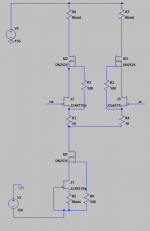
The 725 amplifier is pretty much a blameless with a common mode bootstrap Jfet buffer.
Actually the Jfets are in darlington with the bipolars.
Please send me you depletion mode cascode idea and I'll include it. Or post it here. Whichever. So what to use the for the Jfets?
No I don't think it's difficult and probably no matching of transistor except for the Jfets of course.
It's not difficult to beef up the output. I can think of a couple of way to do that.
That low level input is an op amp set at a high gain. The distortion is through the roof. I don't like it.
Scott made a descrete circuit... I called it the SWOPA. It can be found somewhere around DIYAudio. Scott thought it would do <-120 but I dont know if anyone made one or tested it. With SW's help, it could possibly do the job. It also used 24v rails.
careful selection/matching of input devices is necessary to get extremely low levels of thd+N ..... cant rely on a dc balance pot..... which often can be used to lower 2H but increases 3H in many circuits.
Anyway, SWOPA is a good choice as well to try... as a buffer could be extremely good if predictions are true.
Lets ask SW for help in an OPS for the osc/gen. He's retiring soon and may have more time.
Scott, can you help us design SOTA amp for this ??
THx-RNMarsh
Last edited:
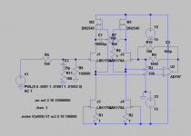
The circuit I used in the NuForce preamp is pretty close. This gives the basic idea. I can send you the complete simulation. Adding the bipolar pair will have higher voltage gain at the input. The low noise pair from Linear Systems worked fine in the NuForce with very low distortion.
I can send you the complete simulation but its a pain to get the transistors into the database. I may have some assembled boards around here as well. It uses more real estate and has more output drive than the Shibasoku.
I can send you the complete simulation but its a pain to get the transistors into the database. I may have some assembled boards around here as well. It uses more real estate and has more output drive than the Shibasoku.
Attachments
Demian, did you ever measure it? With all the circuits david tried and didnt get low enough, it's going to be a really big challenge.
IIRC, the 725 circuit used two Vas stages. Ultra-high olg.... surprised the composite opamp configuration didnt work well enough.
THx-RNMarsh
IIRC, the 725 circuit used two Vas stages. Ultra-high olg.... surprised the composite opamp configuration didnt work well enough.
THx-RNMarsh
Last edited:
I did not have the Shibasoku when I designed that product. All the measurements then were limited by my equipment. The amp has 20 dB of gain and I measured .0006% THD, the limits of my hardware. I'll see if I can get a unit up and measure it again soon.
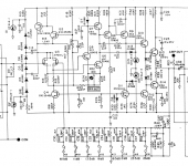
I don't see a second VAS in the 725 circuit (attached). I also attached the phono version of the amp I did for NuForce and a quick test of a FET buffer for an opamp. I can post the ltspice files and my modified parts files if there is interest.
I don't see a second VAS in the 725 circuit (attached). I also attached the phono version of the amp I did for NuForce and a quick test of a FET buffer for an opamp. I can post the ltspice files and my modified parts files if there is interest.
Attachments
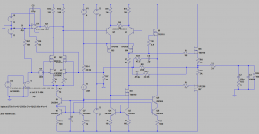
It doesn't show on the simulation but M8 drives an active shield around the high impedance output of the VAS. It also drives C6 as part of the stabilization network. I'm not sure now whats on the PCB. I may have used a gimmick https://www.youtube.com/watch?v=v1wWL6TGWOE . The sim is a mod on the original that had 20 dB of gain and a larger feedback cap there. The sim works with a pretty small error on the RIAA curve. I'm not sure I would make a phono preamp this way today. The FET buffered opamp may be a better choice. It would address the level dependent input cap on the opamp, which is the dominant remaining distortion source, probably for all of this stuff. And I would be tempted to use DSP and correct for the actual response of the phono cartridge.
I did not have the Shibasoku when I designed that product. All the measurements then were limited by my equipment. The amp has 20 dB of gain and I measured .0006% THD, the limits of my hardware. I'll see if I can get a unit up and measure it again soon.
We will need better than .0001% More like <.00005%
Why wouldnt this work or its replacement or similar? -- http://www.ti.com/product/LME49990
-RNM
Last edited:
I did not have the Shibasoku when I designed that product. All the measurements then were limited by my equipment. The amp has 20 dB of gain and I measured .0006% THD, the limits of my hardware. I'll see if I can get a unit up and measure it again soon.
I don't see a second VAS in the 725 circuit (attached). I also attached the phono version of the amp I did for NuForce and a quick test of a FET buffer for an opamp. I can post the ltspice files and my modified parts files if there is interest.
I think Richard is looking at the current mirror. Kind of look like a VAS the way it's drawn.
- Home
- Design & Build
- Equipment & Tools
- Low-distortion Audio-range Oscillator