That's a problem the thermal time constant starts to overlap the frequency and you start to lose. BTW Bob I've given my for real retirement notice effective this holiday shutdown period. A perfect 42.")
CONGRATULATIONS!!
Any chance you'll be at Burning Amp or Audio Aficionados?
Cheers,
Bob
CONGRATULATIONS!!
Any chance you'll be at Burning Amp or Audio Aficionados?
Cheers,
Bob
My wife and I are going on a long vacation, maybe next year.
My wife and I are going on a long vacation, maybe next year.
Scott are going to able to stay away this time?
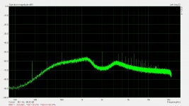
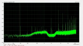
This oscillator is the second generation. I added the capability to function as a high Q band pass filter. In this mode the multiplier is reduced to a two quadrant multiplier operating as a voltage control variable gain inverting amplifier. That's probably not a good description because it just attenuates. No the less the positive feed back is removed and the multiplier controls the damping of the filter depending on the injected level. For -60db input the output is 2.5Vrms.
The fist pic is the output of an EMU0204 which measure -90dBV THD+N. Not that great.
The best the 0204 can do is 0dBu output level.
The second pic is the emu0204 injected into the SVO as a high Q BP filter.
The measured distortion - -100dBV. But the individual harmonic has dropped significantly which suggest the measurement is mostly noise.
Both of the measurement are on the 0.003% (-90dBV) scale. So -90db at 0db ARTA.
From a cleaner source the result should be impressive.
The output frequency is that of the source.
Scott you were asking about this a while back.
Attachments
Last edited:
Hi David,
Nice work!
-Chris
Thanks Chris.
Excellent work David (although I think you meant -120.9 db in Post 5120).
Likewise, congratulations, Scott. Quite the run.
Thanks DPH.
Yes you are quite write I did mean -120.9dBV THD+N.
Chris can you fix this for me.
2KHz is the sweet spot of the generator.
Richard you going to like this. Better than mine.
All scaling the same just 2KHz.
This shows max capability to measure is similar to what I was able to get with that 725D using a spectrum analyzer on the monitor output ... I ranted and raved for months over on the Lounge that we could go to -160 in testing. I relaxed that to -150 for same accuracy as spec. I love your osc. Meets all my needs with variable freq and output level and ultra low distortion. wow. When I had the early version I had to put the unit in a large steel can and isolate it from grounds and many things to see that low without external noise intruding. Have you done anything new/better in the shielding/grounding ?? I know it will always need care in measurement setup for such low levels. Just curious if you did anything more?
THx-RNMarsh
No nothing special with the shielding.
I moved the cable modem to another room and it's SMP along with it.
The first changes on the proto are cemented on the board now. Maybe that helps. Now I have a whole new set of changes to do. It keeps evolving.
The so called infinite sample and hold is gone and replaced with a really good track and hold
amplifier. This is for the integrator only. The proportional is a short direct loop to the multiplier ADC input.
That needs a bit of explaining it's an unusual control set up. At any rate the digital sample and hold was not needed.
I live about 50 miles from the hydro dam. Maybe that makes a difference. Who knows.
I've had really bad measurement days too.
It's variable frequency but fixed output.
Last edited:
Thats great. Some may not know but we/I went thru many gyrations trying to get low enough measurements... I started with AP Sys One dual domain and modified sound cards. Then modified an HP339A, then ShibaSoku and various Panasonic and AP 2722. Along the way, added notch filters and finally K-Hite generators. It finally came down to needing a better osc/generator. Why all this? because I couldnt measure the distortion of a little headphone amp I made. With the best instruments, I STILL cant measure the distortion.... I used the instruments to fine tune the circuit. Now, with a gain of 12 I just amplify the AP osc/gen without seeing any added distortion level or harmonics. [See below] Now I need a better osc/gen. And, here we are ---- I will now measure to lower levels than the internal osc/gen of the AP. I am very thankful that there is so much talent here to take on the challenge and tasked themselves to do their best. I continue to learn thru the process from others who have gone before me and into the future. We all learn and get something from the shared support and process.

THx-RNMarsh
THx-RNMarsh
Last edited:
I've tried buffered op amps. Composite op amps. Composite DSL amplifiers. Discrete amplifiers etc.
I got tired of throwing money at it.
All of these were good and would work very well for audio but not quite good enough for this.
The issues are not necessarily with the amplifiers. Some of this is from expectation of impossible requirements.
If I could recreate the Shibasoku amplifier. I could use that and call it a day.
Last edited:
Thats a good idea. And use the new jFETs to replace the obsolete ones used in (and maybe made for) the 725. My tweaked amp is way too hard to get as low as I have it. Not really reproducible in any practical sense. Took hundreds of devices each to sort thru and then fine tune circuit.
What is the output voltage and Zo of your osc/generator?
THx-RNMarsh
What is the output voltage and Zo of your osc/generator?
THx-RNMarsh
Last edited:
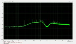
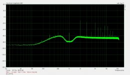
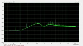
A couple more at 997Hz. The emu output is cleaner at this frequency.
Pic 1 emu @ 997Hz -120.9dBV THD+N
Pic2 is 997Hz through the BP filter. -119dBV THD+N
Scale is -90dBV
Good thanks, I suspect the limits of this will be related to any number of things including the amplifiers. I admire the energy in doing THD at full scale but I still think bridge or other pre-nulling techniques will always win for raw numbers at a single frequency.
Hi Frex,
I was very careful to build it following your BOM. Mostly Digikey parts. Needless to say, I was surprised to see 5 KHz. That's not a welcome frequency since I use an HP 339A, and switching a decade in frequency is easy. 5 KHz isn't.
They both work, but the 2nd harmonic is higher than it should be as Jan noted.
Jan, you could do that with a normal board. Just run the wires to your switching assy from the PCB, same for the level control.
-Chris
Hello Chris,
I looked today what can cause your issue, and when reading my 10kHz bom file if think i found from where it come.
The capacitors C35,C38 and C39 appear in bom list "as mounted while they must not be mounted.
(the qty of 3 is right, but they are 6 caps in bom). Schematics is ok.
So, for correct 10kHz operation you should only remove these three caps and all will become ok.
Sorry for this mistake.
If necessary, the corrected updated bom can be downloaded here.
The 2nd may be a few dB optimistic due to the passive notch, but still 1st class performance I think.
Frex, if I would build this I would make it switchable for a couple of spot frequencies, make sure the level control is a good quality pot with a knob rather than a trimpot, and also include a balanced output connector, an XLR or better yet a combination XLR/TRS.
And of course power it with a SilentSwitcher ;-)
Any chance you will make an alternative packaging for some standard box with panel drawings for such a 'deluxe' version?
Jan
Hello Jan,
I think also that your SilentSwitcher seem to be very well fitted for this use.
The oscillator PCB is quite small (92x75mm) and probably many enclosures could host two with the SilentSwitcher PCB and few connectors.
The PCB has been designed to fit in a low cost aluminum case from Hammond (1455J1201),
but maybe a bigger one (from Hammond) also can do the job for what you want (I hope to have answered well).
For panel drawing, i provide a sticker made with printable sheet. If your anclosure design is different, the original file (in svg format) can be modified easily.
If needed, i could help for that.
Regards.
Frex
- Home
- Design & Build
- Equipment & Tools
- Low-distortion Audio-range Oscillator