The KH4000 family of oscillators settle to the target level in less than one cycle even at 1 Hz. And still have very low distortion. If I can find the schematics I'll post them. Its an old design and all discrete so pretty involved but is not using a sample and hold.
In less than one cycle? That's impressive.
The KH4000 family of oscillators settle... in less than one cycle even at 1 Hz. And still have very low distortion. If I can find the schematics I'll post them.
Any luck? I checked the Krohn Hite site and the manuals there have the circuit description removed.
Best wishes
David
I was referring to the KH4000 and KH4024. I do have the manual here somewhere. The 4100 has similar performance. The 4200 is a different product with a different operating range.
As I remember (its been many years since i read the description) they use a technoique of injecting a charge to boost or cut the level. No FET or analog multiplier. All the details beyond that are in the elusive manuals. They do have good circuit descriptions.
As I remember (its been many years since i read the description) they use a technoique of injecting a charge to boost or cut the level. No FET or analog multiplier. All the details beyond that are in the elusive manuals. They do have good circuit descriptions.
Sounds like they are resetting the initial conditions of the oscillator (i.e. the voltage across the/charge of the capacitors) once per cycle. One of the few relevant reference I know is: RC OSCILLATOR WITH EXTREMELY LOW HARMONIC DISTORTION | Vannai | Periodica Polytechnica Electrical Engineering.As I remember (its been many years since i read the description) they use a technoique of injecting a charge to boost or cut the level. No FET or analog multiplier. All the details beyond that are in the elusive manuals. They do have good circuit descriptions.
Samuel
...The 4200 is a different product....
No FET or ...multiplier. All the details beyond that are in the elusive manuals.
I must admit I was surprised not to see any obvious FET or multiplier in the 4200 circuit.
I didn't look too closely at the circuit because I had noticed the 4200 was different and I wasn't sure how relevant it was.
But your brief description sounds similar, now I am even more curious to see the manual.
... One of the few relevant reference I know is: RC OSCILLATOR WITH EXTREMELY LOW HARMONIC DISTORTION | Vannai | Periodica Polytechnica Electrical Engineering.
Thank you for the reference.
Best wishes
David
PS. Also thanks to Anders for the KH4200 connection
Last edited:
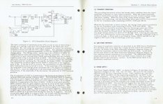
KH4024
I found the manual. I scanned the circuit description and I'll make a complete scan in a few days. Unfortunately its an old document and a decent scan becomes a big file, too big for DIYAudio. I'll try to figure out a workaround..
Let me know if the attached image is readable. send me a PM and I'll send the complete scan when i have it done, hopefully by the weekend.
Attachments
... is readable. send me a PM and I'll send the complete scan when i have it done, hopefully by the weekend.
Thank you, even better is to take Jan's offer and post it there so everyone can read it and we can share.
As already commented, it's soft focus but readable.
Best wishes
David
Jan has now posted it here: Measurement Means and Methods | Linear Audio NL
Its operation is not straightforward so some study would needed to understand that part of the circuit. I believe the distortion limits of that design are feedthrough from the agc pulses but I have not had one for many years so that all just fuzzy memory.
Its operation is not straightforward so some study would needed to understand that part of the circuit. I believe the distortion limits of that design are feedthrough from the agc pulses but I have not had one for many years so that all just fuzzy memory.
OK, I can do French and have help for Deutsch and, less easily, Italian, Japanese, Dutch, Spanish, Danish, Chinese and a few others (have to love a multicultural society).
So any dialect will do. David
@ Dave Zan,
You probably know this but careful when using the term dialect for language.
As they are different. And example from my colleague from India, they have
something on the order of 700 dialects which are different than Hindi, the
formal language.
Auf Deutsch, the official language is "HochDeutsch" or High German.
This is distinctly different than Low German or the other dialects.
The other German dialects can be difficult for German's and other
people to understand.
Funny, when I was traveling I heard a couple talking around a fountain
in some unusual language I wasn't familiar with, I asked them,
"excuse me, where are y'all from?"
"Scotland," they replied.
I have had a think about optimization of the leveler loop.
Do people just use trial and error or has anyone actually plotted the return ratio in (LT)Spice with a Tian probe or similar?
David
I didn't use the term "dialect" accidentally, my partner speaks Schweizerdeutsch.
Or, more commonly, Schweiztralian - a dialect of her own.
I know all about "difficult to understand"") but it has improved my vocabulary.
but it has improved my vocabulary.
Best wishes
Do people just use trial and error or has anyone actually plotted the return ratio in (LT)Spice with a Tian probe or similar?
David
...the term dialect...
The other...dialects can be difficult for... other people to understand.
I didn't use the term "dialect" accidentally, my partner speaks Schweizerdeutsch.
Or, more commonly, Schweiztralian - a dialect of her own.
I know all about "difficult to understand"
but it has improved my vocabulary.Best wishes
Do people just use trial and error or has anyone actually plotted the return ratio in (LT)Spice with a Tian probe or similar?
SPICE is not of much use (at least in small-signal mode), that's something you need to model by hand. First step is to linearize the oscillator at the operating point (the oscillator responds exponentially to a disturbance, so is actually a pretty nonlinear feedback system). The more usable leveling loop topologies also include sampling and some fixed delay, which needs to be accounted for.
Details can be found e.g. here:
Vannerson: Fast amplitude stabilization of an RC oscillator
Vannerson: A low-distortion oscillator with fast amplitude stabilization
Filanovsky: A comparison of two models for an oscillator with an amplitude control system
Taylor: Amplitude stability and distortion in thermistor-controlled oscillators
O'Dell: Instability of an oscillator amplitude control system
Van der Walt: A Wien-bridge oscillator with high-amplitude stability
Maneechukate: Wide-band amplitude control of the second-order oscillator circuit
Cattell: Adaptive feedforward cancellation viewed from an oscillator amplitude control perspective
Meyer-Ebrecht: Schnelle Amplitudenregelung harmonischer Oszillatoren
Tong: Audio modulation section for an RF signal generator
This should cover most you ever wanted to know about oscillator leveling loop dynamics.
Samuel
SPICE is not of much use... you need to model by hand. First step is to linearize the oscillator
An LTSpice AC analysis does linearize about the operational point, that is, of course, how the usual return ratio plot is done.
Question is how to apply it here?
We don't really need a Tian probe, the control lop should be close to unidirectional so a simple probe will do.
An extended TRAN simulation with a little "bump" on the control element would be informative but incomplete.
(the oscillator responds exponentially to a disturbance, so is actually a pretty nonlinear feedback system)
The system is indeed quite non-linear.
Mark Williamsen has a paper in "International Journal of Circuit Theory and Application" where he uses the ln(error) for feedback.
This makes a nice linear system and he has excellent predictions of loop behavior when heavily perturbed.
But for a loop that's close to equilibrium I expect the disturbance to be very small, quasi-linear.
Would this not be sufficiently close for a oscillator that is used steady state?
The more usable ...some fixed delay, which needs to be accounted for.
I have read the Vannerson paper that discusses this but I have an idea for an improved implementation of a sin^2 + cos^2 leveler so I don't need to deal with delay.
Thanks for the other references, some I already have and the rest I will try to find.
But I meant had it been done by anyone in this thread?
Best wishes
David
Last edited:
The presenting issue was transient settling time not distortion. The 4400 settles much slower and would be of little use at or below 1 Hz. The 4000 can go much lower and would need a faster agc.
Sent from my SGH-M919 using Tapatalk
I didnt notice a Much slower condition. But, remind me again what we need 1Hz or lower for?
THx-RNMarsh
I didnt notice a Much slower condition. But, remind me again what we need 1Hz or lower for?
THx-RNMarsh
Do you mean 'we' as in low distortion oscillators or is there any use for sub Hz oscillators?
- Home
- Design & Build
- Equipment & Tools
- Low-distortion Audio-range Oscillator