Do you remember whether it was 2nd or 3rd that was too high, or both? The non-inverting buffer is a very difficult problem at -120 and below. I'm dealing with those issues on the Boonton. The differential input is fine on the X1 range, but X10 causes a significant increase in 3rd harmonic. My guess is the source impedance of the divider and the input cap modulation of the opamp are causing the problem. In the Shibasoku they went to extremes to cascode jfets as followers into the bipolar input diff pair. I think this is what it will take to make that buffer work below -120 db harmonics. i don't think this will be easy in an opamp. I have sketched out a discrete/opamp combo for this but it felt like an extreme effort. Below and attached. It felt odd to use so many discrete parts with an opamp.
Demian can you paste the non LT models to the schematic when you post .asc?
Cheers,
have you tried Class A biasing the output?
even just a pull down R to the rail may make a difference by eliminating the Class B half wave supply currents
ccs is better, 2 transistor bjt perform well without device selection needed with fet
best is push-pull
I tried with a resistor from output to rail with not much effect at all
What I have in mind is to set it up as you showed in you thread. The boot strapped current source. For this I think a PCB. The buf634 is attractive for it's simplicity of thermal management. The buff634 is available in to220 like package.
I haven't tried a composite arrangement with these buffers rather than just rapping the FB around them. The board I have is a small pcb I put together just for evaluation a couple of years ago.
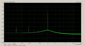
Below is and LME49600 in a loop with a 1611. RB resistor is 470 ohm and shunt is 200 ohm.
Output is 8.375Vrms and input 2.5Vrms. Non inverting mode. The load is just the FB components.
Attachments
Demian can you paste the non LT models to the schematic when you post .asc?
Cheers,
Sure. Attached. Unzip and put into the directory that matches the file name. For the discrete components edit the files in /lib/comp and add from the attached Additional FETs.txt file. (I'm too lazy to use the ".include" to add other libraries.)
(These notes are as much for me as anyone. I know I'll forget how to do this by the time I need to do it again.)
Attachments
The bootstrapped current source combined with a follower is what the KH4400 uses. It works pretty well but for 600 Ohms I got better results replacing the 5534 + discrete with an LME49990 on an adapter and bypassing the discrete stuff.
Using it on the output of an opamp or buffer would require some understanding of whats inside the device, or at least some experimentation. The new generation opamps are not made with funky lateral PNP's.
One thought would be to use the AD797 with a buffer and use Scott's cap trick around it all to cancel the output distortion. He said it would work somewhere about 3 million posts ago.
yes those show paralleling op amp/buffer outputs in push-pull with a added offset V giving a Class A standing current across the 2 small value output summing R
I have put the paralleled buffers both inside of a composite loop with a OPA627 up front
if you want to explore AD797 a little more I did a simplified sim of the AD797, its decomp/"distortion cancellation" Cn http://www.diyaudio.com/forums/solid-state/123613-class-biasing-ad797-6.html#post1525757
of course I didn't have anything like the real IC Q models so its just a topological sketch
Last edited:
David -- this design might also just do your osc some justice: --
Weiss Engineering Ltd.
OP1-BP datasheet on circuit design.
THx-RNMarsh
Seems to be a dead link at least for me. Been having a lot of trouble with DIYA lately as well.
Takes for ever to load a page.
I am having the same problem today with this web site, but I found the device RNMarch is referring too = stellar performance. Looks like the device is meant for horizontal mounting, re: p27 and as shown in the pic, assume to attach it to a daughter pcb. I was surprised to see the HS fins running horizontally not vertically = hum!!
Okay i see what they did, they attached the HS to the two TO-126 sized devices. Sometimes not so easy to find the exact AL extrusion one would want.
http://www.weiss.ch/files/downloads/op1-bp/OP1-BP-Datasheet-R1.pdf
Okay i see what they did, they attached the HS to the two TO-126 sized devices. Sometimes not so easy to find the exact AL extrusion one would want.
http://www.weiss.ch/files/downloads/op1-bp/OP1-BP-Datasheet-R1.pdf
Last edited:
I was surprised to see the HS fins running horizontally not vertically = hum!
Why should this cause hum? Anyway, I've designed an improved version by now (OP-BP2, no datasheet available as the basic electric specs are the same) which uses a much larger and horizontally mounted heatsink.
Samuel
Hi Samuel, I mean hum, as in I scratch my head as too why!!, not AC line hum, sorry for the confusion, poor wording ")
On this low THD buffer discussion, I recently bought a HP 11715A test set assembly(11715-60001) for some RF work I am doing. It has impressive linearity for the target FM commercial band, (88-108MHz) <0.025%THD, but it has a 50 input Z (something to play with) for the 400MHz VCO (gets divided down by 4 for the FM band). This creates an overload for my Amber 3501 oscillator, so I was looking around at buffers to drive the stock 50ohm input Z. Obv. the easiest for me is the LME49600 or 49610, which is what I will probably use, to keep it cheap and simple.
While I was looking around for the buffer, I was wonder what they use in a HP 3325A function gen (03325-66514,A14 output amplifier assy), as it is spec'd for flatness,level, freq. response testing of the HP 11715A and a HP 8901A that I own. I have know idea of the THD performance of that particular design, but I was intrigued by it none the less, will try to sim that design and see how it performs.
Last edited:
Why should this cause hum? Anyway, I've designed an improved version by now (OP-BP2, no datasheet available as the basic electric specs are the same) which uses a much larger and horizontally mounted heatsink.
Samuel
As per Scott Wurcer's suggestion -- Would it be possible to use your OP-BP2? Would you email schematic/parts so I could build one. Or better yet buy one or two all ready made from you?? It seems to be the SOTA and the oscillator of David's could use it to drive low Z loads. I could try it in the front end of analyzer.
BTW -- How is your osc coming along?
THx-RNMarsh
Last edited:
David -- this design might also just do your osc some justice: --
Weiss Engineering Ltd.
OP1-BP datasheet on circuit design.
THx-RNMarsh
Yes this would probably do. It's not spec'ed for distortion below 600 ohms but it beats developing one my own. There's other things I'd rather be doing and spending on the cost of developing.
What's the cost on these Samuel?
I have checked the datasheet of the OP1-BP and the parameters are excellent. Wish I was able to measure such low distortions as Samuel. I finish at -130dB even with notch filter.
Build one of Samuel's notch filters.
I have a Shibasoku 725C on it's way. My resolution should improve some.
- Home
- Design & Build
- Equipment & Tools
- Low-distortion Audio-range Oscillator