The Krohn Hite 4000 series are state variable oscillators, dating from the '60s and '70s that had .001% distortion. They used 25V supplies and some pretty sophisticated discrete circuitry. The dominant distortion on them was from the AGC's sampling pulse.
I've only looked at the newer KH designs which I thought were bridged T. I'll look again.
I haven't seen a State Variable the doesn't use an output amp. They typically have to run at a lower output level to obtain a low level distortion. No more than +10dB for mine to get the harmonics below -140 b/t 1k and 10KHz. Victor's oscillator I think has a max of 2.67Vrms IIRC and would require a post amp for higher levels. If +10dB is all that's needed then no post amplifier is required.
So we are comparing apples to apples, B Cordel's uses a post amp. The gen in the Sys One
uses a post amp and IIRC so does the Tek SG. All SVO's. IIRC the KH uses a bridged T which like the HP339A operates at a high output level of about 20Vpp.The 339a has a buffer amp.
600 ohms is a very old standard. It seemed to gradually disappear with the onset of op amps and as discrete circuitry was replaced by IC's in the 70s and early 80s. It's still used in studio and broadcasting but not like it was.
I think 50 ohms would be more useful. 31.6Vrms is a lot and I don't know if I'm going there but I suppose it would be useful for bringing out distortions in passive components.
I pointed out to Dick Moore the 339a distortion will rise as the attenuator is loaded even though the buffer amp sees a constant 600 ohm load. I haven't confirmed the cause or isolated the cause to the attenuator network. A Best guess would be as Samuel has pointed out the power coefficient of the resistors. It is quite a significant rise in distortion.
This design has not been to simply copy designs or methodology of the past but more of a study on what it takes to get low distortion in an oscillator while applying SOTA technology. And of course to have a useful piece of test gear in the end. I had this in mind while doing the study on the lamp multiplier. There are no front panel controls. It operates entirely from PC UI control.
Samuel how are you going about determining R values for minimizing the effect of power coefficient of the resistors. Obviously physical size of the resistor must play a part. Would it be useful to mount resistors over a copper plane to spread the heat or is it this strictly an instantaneous power effect?
600 ohms is still useful as a compromise impedance level for constant-impedance step attenuators, since its degree of loading allows relatively high output voltage levels without resort to a high-power output buffer. To have such constant-impedance attenuators at 50 ohms reuires significantly more power for a given voltage swing. It is true that there is no longer much sacred about the number 600 ohms. I believe that the origin of the 600 ohm number was that it was the chosen characteristic impedance of open-wire telephone lines.
I tend to doubt that power coefficient of resistors is responsible for what you are seeing; I don't think the 339A is fundamentally low enough in distortion to unmask that effect unless they used really crappy resistors. I think the power coefficient distortion only occurs at low frequencies unless there is some phenomenon in them that I am not familiar with. Does the rise in distortion with attenuator loading increase similarly on all steps of attenuation, or just the maximum output step? Who knows, maybe the switch contacts are dirty.
Cheers,
Bob
I'd have to dig into it again to be certain. It was a long time ago and didn't care much at the time. Just thought it was rather odd and not easily explained. Dick confirmed the same on his 339a. He didn't believe it when I mentioned it to him so we both checked twice.
I don't think HP used any crappy parts in the oscillator except perhaps the inter stage coupling caps. Switches had been cleaned but given their age....
Come to think of it I used a wire wound pot to do the loading. Maybe it was the pot?
Last edited:
As a practical matter for consumer audio --- and that Most opamps/IC can drive 1K Ohm without significant increased distortion --- lets use 1k Ohm for the worst case load and not 600 Ohms.
Most consumer electronics have input Z much higher than 1K and so I wouldnt worry too much..... just an attenuator is all most would ever need.
THx-RNMarsh
Most consumer electronics have input Z much higher than 1K and so I wouldnt worry too much..... just an attenuator is all most would ever need.
THx-RNMarsh
I have seen the distortion of an opamp rise switching the source impedance from 50 Ohms to 600 Ohms. I believe its an embodiment of Early effect. Not all opamps show a lot of this in non-inverting mode but some do. And most practical pots are in the 10K to 50K range, not 600 or 50. Also the higher source impedance will introduce level and frequency related issues. Since we can now build -120 dB THD with the potential of flat response to 1 MHz the source devices need to be pretty free of errors to validate the performance. 10K with a 600 Ohm source impedance will produce an error, so will 100 pF of cable. Perhaps the real answer is remote sensing?
I've only looked at the newer KH designs which I thought were bridged T. I'll look again.
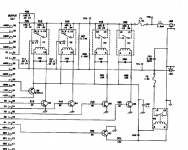
I have a manual for the older KH4000 series here somewhere. I'll scan it and make it available, maybe this weekend. It's not in the easiest form to scan so I'm not rushing. They do go down to .001 Hz and recover from range switching almost instantaneously.
Then there's no simple formula or method to this. Found empirically.
I've found one or two papers that show the calculations involved for thin films over a solid substrate, but that's of little help as we don't have the needed parameters (e.g. geometry) for available commercial resistors. In the end, what we want is actual production spread/distribution, so this needs to be measured anyway.
Samuel
.... Also the higher source impedance will introduce level and frequency related issues. Since we can now build -120 dB THD with the potential of flat response to 1 MHz the source devices need to be pretty free of errors to validate the performance. 10K with a 600 Ohm source impedance will produce an error, so will 100 pF of cable. ......
I would also forget about 600 Ohms as a source Z. No need for it in consumer electronics. If you need it for some reason, add it in but dont build it in. Much lower Zo is best.
Low C test cables can be found/used and DUT distances can be easily kept to well under 100pf, if needed.
The osc is for extreamly low distortion T&M and not for measuring freq response out to 1MHz and beyond......BW/freq response testing with ADC/FFT gear is limited anyway.
-RM
Last edited:
I have seen the distortion of an opamp rise switching the source impedance from 50 Ohms to 600 Ohms. I believe its an embodiment of Early effect. Not all opamps show a lot of this in non-inverting mode but some do. And most practical pots are in the 10K to 50K range, not 600 or 50. Also the higher source impedance will introduce level and frequency related issues. Since we can now build -120 dB THD with the potential of flat response to 1 MHz the source devices need to be pretty free of errors to validate the performance. 10K with a 600 Ohm source impedance will produce an error, so will 100 pF of cable. Perhaps the real answer is remote sensing?
I'm not getting the remote sensing thing. What do you mean?
50 or 600 ohms is a gross impedance mismatch to 10k or 50k ohms. There is strong possibility what you're observing is destructive signal reflection from the mismatch. I believe the old 600 standard was for this reason. It was a real pita to have to bring every input and output to 600 ohm. I think it was phased out to save the cost. It is very real concern in RF and one of the things I have to know about to do my job. I deal with it daily among other things in the 25 square kilometers of RF transmission line I'm responsible for maintaining. The effect is much more pronounced at the lower end of the RF spectrum 5mHz to 45Mhz band for us. Lower frequencies propagate more easily because they require less energy to propagate and the cable capacitance has a lesser effect on them. The cable causes a delay VOP, velocity of propagation, which is a percentage of the speed of light. Most coax cable we use is typically 0.87 VOP - 87 percent. In audio the small cable delay is probably of no consequence because the wavelengths are long but reflections exist from DC to daylight. The magnitude of reflection is proportional to the mismatch, To get a sense of this put a graphical TDR on 100' of coax and measure with the cable end shorted, then open and finally terminated with a matching resistor.
I'm not clear why this is largely ignored in the audio realm.
On the 50 ohm attenuator; I did some back of the envelope calculations on this last night.
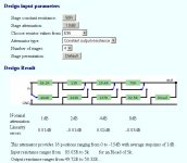
For a 20Vpp signal we would require a 4W resistor at 50 ohms. For a constant 50 ohm output impedance the input resistance will vary increasingly and the power requirement lessens but we would still be looking at 1W to 2w parts. To do it right 0.1% parts would be required. I think I have to agree with Bob that the power requirements make it to costly.
If 50 ohms is required padding the output with T networks would be a better option but it would still require a headphone size power amp to do it which is not unreasonable.
I'm not clear why this is largely ignored in the audio realm.
On the 50 ohm attenuator; I did some back of the envelope calculations on this last night.
For a 20Vpp signal we would require a 4W resistor at 50 ohms. For a constant 50 ohm output impedance the input resistance will vary increasingly and the power requirement lessens but we would still be looking at 1W to 2w parts. To do it right 0.1% parts would be required. I think I have to agree with Bob that the power requirements make it to costly.
If 50 ohms is required padding the output with T networks would be a better option but it would still require a headphone size power amp to do it which is not unreasonable.
we usually don't care about precise level in audio - we rapidly accommodate, even pros have a hard time setting levels to better than ~1 dB (~10%) "by ear"
relative level only has to be matched to ~1% to be below hearing threshold with much larger errors inaudible over smaller ranges of audio frequency, especially near the extremes of our frequency range
relative level only has to be matched to ~1% to be below hearing threshold with much larger errors inaudible over smaller ranges of audio frequency, especially near the extremes of our frequency range
At audio frequencies the usual reason for not matching impedances is that the wavelengths are so long there won't be reflections. The 600 Ohms system for pro-commercial audio largely falls out from completely passive mixing-and eq networks. A console from the 60's would have amps and the input and output and passive attenuators (600 Ohms) and passive eq networks. Anything that was not 600 Ohms would upset the whole applecart.
Early mike mixers were passive at the mike level (!!) because amplifiers were so precious. They were at 150 Ohms or 250 Ohms.
The introduction of active equalization and active mixing networks in the '70s changed all of that, made the consoles much cheaper as well. Today a lot of it is in the digital realm and except for managing headroom anything is possible.
The phone system is 600 Ohms even though the wires are not. Look at 300 Ohm Twinlead and rescale for 600 ohms. . . Again 600 Ohms is for things like the hybrid transformer to work. Magic like full duplex on 2 wires needs this stuff.
Studio practice changed at the end of the last millenia because it was realized that the passive networks were gone and the losses from a matched network did not bring any benefits. I think current best practice is 25 or 50 Ohms source and 10K load balanced systems. An extra 6dB SNR is not to be sneezed at.
Precise level can be an issue at the interface between measurements and listening. Its also important for making sure the ADC/DAC is operated where you want. It is accepted that a .4 dB level variation over the audio spectrum can be audible. Some claim less. If I can get .1 dB or less (easy) then I will do it, but I need to verify. http://courses.physics.illinois.edu/phys406/Lecture_Notes/P406POM_Lecture_Notes/P406POM_Lect5.pdf (Really good compendium of all the acoustic perception stuff)
Studio practice changed at the end of the last millenia because it was realized that the passive networks were gone and the losses from a matched network did not bring any benefits. I think current best practice is 25 or 50 Ohms source and 10K load balanced systems. An extra 6dB SNR is not to be sneezed at.
http://courses.physics.illinois.edu/phys406/Lecture_Notes/P406POM_Lecture_Notes/P406POM_Lect5.pdf (Really good compendium of all the acoustic perception stuff)
Thanks for the paper. That's an entire course. Not something I can get in one reading.
I'll have dig up some physics on the electrical reflection thing to get a better understanding of the relationship between wavelength and reflection.
It's possible that what I observed with the 339a attenuator was caused at the receiving side of the setup.
I forgot about the passive network of the past and the conservation of actives. We've become spoiled from jelly bean op amps and the like or mabey fortunate would be a better term.
25 - 50 ohms to 10K is definitely leaning towards the efficiency side of things. But what about this observed input distortion? Was that just a point about keeping the driving impedance low? There are several ways of handling the attenuation into a low Z. One is a high voltage into a passive R network. This probably gives the best SNR and distortion ratio.
Another is to handle the gross attenuation on the low side by gain and or attenuation and the fine attenuation with a passive network. Or handle the fine attenuation on the low side and the gross with a passive network. Which would be best vs cost, complexity and performance?
The input distortion is real and shows up to varying degrees with all electronics. Everything from the CV curve of a semiconductor junction to Miller cap in a tube will reflect at some level. When you are looking at -140 dB it all matters. The lower source impedance attenuates the input non-linearity.
Using an amp to source the signal works at higher levels but its noise floor limits everything at lower levels. A resistor network is really the only option. It does not need to be constant impedance as long as the output is low impedance.
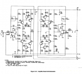
My Boonton has the ability to drive 16V into 50 Ohms and pretty low distortion. A variation on that design (bridged tied load) is not that hard to do, you just need more forward gain and enough heat sink for the output devices. Possibly wrapping something like the TPA6120A2 http://www.ti.com/lit/ds/symlink/tpa6120a2.pdf inside a loop with an LME49990 (compensation will not be simple) will give 700 mA peak. And the chip is good for .0006% THD without help and 100 MHz power bandwidth. it was designed for DSL where some money can be made.
Using an amp to source the signal works at higher levels but its noise floor limits everything at lower levels. A resistor network is really the only option. It does not need to be constant impedance as long as the output is low impedance.
My Boonton has the ability to drive 16V into 50 Ohms and pretty low distortion. A variation on that design (bridged tied load) is not that hard to do, you just need more forward gain and enough heat sink for the output devices. Possibly wrapping something like the TPA6120A2 http://www.ti.com/lit/ds/symlink/tpa6120a2.pdf inside a loop with an LME49990 (compensation will not be simple) will give 700 mA peak. And the chip is good for .0006% THD without help and 100 MHz power bandwidth. it was designed for DSL where some money can be made.
The input distortion is real and shows up to varying degrees with all electronics. Everything from the CV curve of a semiconductor junction to Miller cap in a tube will reflect at some level. When you are looking at -140 dB it all matters. The lower source impedance attenuates the input non-linearity.
Using an amp to source the signal works at higher levels but its noise floor limits everything at lower levels. A resistor network is really the only option. It does not need to be constant impedance as long as the output is low impedance.
My Boonton has the ability to drive 16V into 50 Ohms and pretty low distortion. A variation on that design (bridged tied load) is not that hard to do, you just need more forward gain and enough heat sink for the output devices. Possibly wrapping something like the TPA6120A2 http://www.ti.com/lit/ds/symlink/tpa6120a2.pdf inside a loop with an LME49990 (compensation will not be simple) will give 700 mA peak. And the chip is good for .0006% THD without help and 100 MHz power bandwidth. it was designed for DSL where some money can be made.
I'll have a look at that IC.
Would it feasible to run those amps off single supply. Use two IC's with a dual wound secondary transformer for supply. Each amp on it's own winding with both amps floating, one inverted from the other. Then it would be possible to short one output to ground for single output use with no lose of output amplitude. I think with a composite arrangement we could get that distortion down two orders of magnitude 1kHz - 10kHz.
I prefer the passive attenuation for the said reason.
I found this online calculator for a log network. 4 relays get us 16 dB in 1dB steps at nominal 50 ohm constant output impedance and all resistor values below 500 ohms.
Logarithmic Attenuator Calculator
Attachments
Last edited:
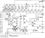
I would just lift the architecture of the Boonton's oscillator and output. It has a high res FET based attenuator (swap for relays) a power amp with bridged load drive in a floating setup. It really works. Let me know if you need more details.
Attachments
The phone system is 600 Ohms even though the wires are not. Look at 300 Ohm Twinlead and rescale for 600 ohms. . . Again 600 Ohms is for things like the hybrid transformer to work. Magic like full duplex on 2 wires needs this stuff.
Bear in mind that the phone system long ago used open-wire transmission on poles where the wires were feet apart. That's what I was referring to. Scaling 300 ohm twinlead probably gets you there.
Cheers,
Bob
I'm just going to try 2 or 3 50/50 dividers and then a very high quality low Z pot.
BTW IC with .0006% will not be good enough. My tweeked KH are lower. You would need at least another zero or two below that.
If the low Z pot isnt low enough, an add-on buffer config opamp could be extreamly low THD and noise.
THx-RNMarsh
THx-RNMarsh
BTW IC with .0006% will not be good enough. My tweeked KH are lower. You would need at least another zero or two below that.
If the low Z pot isnt low enough, an add-on buffer config opamp could be extreamly low THD and noise.
THx-RNMarsh
THx-RNMarsh
- Home
- Design & Build
- Equipment & Tools
- Low-distortion Audio-range Oscillator