First, Viktor's oscillator uses the power supply to make the reference for the AGC. And that reference voltage also sets the output level through the pot. This means several things. Most important if the supply voltage drops below the minimum for the shunt regulators the regulation is effectively gone and supply noise can get through. Second the SNR in the output and probably a number of other aspects are related to the output level. I have noticed that the distortion skyrockets when the supply drops out of regulation.
There will be thermal effects at turn on and it may take a few minutes for the oscillator to settle. The frequency will actually shift a little.
I noted somewhere mods to use an LM317 as a current source for the supply which will further isolate it. It also extends the life of the batteries. I have the oscillators in a cast aluminium box and I need to isolate the box from anything near or noise can enter via the shield.
The spreading at the base of the fundamental is normal and an indication of several thing. First the Q of the oscillator, second the phase noise of the oscillator and third, the window function of the FFT. The internal oscillator won't show most of those because its synchronous with the sampling of the ADC.
The QA400 wants 1V RMS in which is at the bottom of the range for the oscillator. I think the oscillator works better at the top of its range. I use maximum resolution ad 48K on the QA400 when measuring with it. Its not adequate to measure the distortion of one of these oscillators directly.
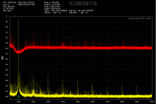
Here is a shot I just took. The yellow is the QA400 fed from my Viktor 995 Hz oscillator at .7V RMS (full output through a -10 db 600 Ohm atteunator), the red is the distortion residual of the Shibasoku 725D of the same signal (they were connected in parallel). For the 725D 0dB is -100 dB so the -30 dB second harmonic is actually -130 dB. I hope this helps.
There will be thermal effects at turn on and it may take a few minutes for the oscillator to settle. The frequency will actually shift a little.
I noted somewhere mods to use an LM317 as a current source for the supply which will further isolate it. It also extends the life of the batteries. I have the oscillators in a cast aluminium box and I need to isolate the box from anything near or noise can enter via the shield.
The spreading at the base of the fundamental is normal and an indication of several thing. First the Q of the oscillator, second the phase noise of the oscillator and third, the window function of the FFT. The internal oscillator won't show most of those because its synchronous with the sampling of the ADC.
The QA400 wants 1V RMS in which is at the bottom of the range for the oscillator. I think the oscillator works better at the top of its range. I use maximum resolution ad 48K on the QA400 when measuring with it. Its not adequate to measure the distortion of one of these oscillators directly.
Here is a shot I just took. The yellow is the QA400 fed from my Viktor 995 Hz oscillator at .7V RMS (full output through a -10 db 600 Ohm atteunator), the red is the distortion residual of the Shibasoku 725D of the same signal (they were connected in parallel). For the 725D 0dB is -100 dB so the -30 dB second harmonic is actually -130 dB. I hope this helps.
Attachments
Yes, that definitely helps. When I received the oscillators from Viktor their pots were turned to max. I checked the Vrms of their output with a DMM first and dialed it down to a level the QA400 could handle. What you said makes sense, I'll try measuring the Viktors at different pot settings using the QA190 in between. I'll also look for your post on the LM317. Thank you.
Edit: I just found your post 2 pages back (my bad) post #3562 where you outline how you got them to work for you. Sorry for the miss but thanks for your help.
Edit: I just found your post 2 pages back (my bad) post #3562 where you outline how you got them to work for you. Sorry for the miss but thanks for your help.
Last edited:
Active Notch Filter
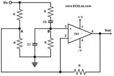
So you're using the active notch filter from the Shibasoku and the passive notch filter from the B&K as your choice for twin t filter? I see Viktor shows his setup in his description and he's using a passive twin t notch filter as well. Would a twin t such as the Fliege work? I think I saw a thread about a variable notch filter by Dick Moore, is that a better choice?
High Speed Active Notch Filter Fliege Texas Instruments
http://www.ti.com/lit/an/slyt235/slyt235.pdf
First, Viktor's oscillator uses the power supply to make the reference for the AGC. And that reference voltage also sets the output level through the pot. This means several things. Most important if the supply voltage drops below the minimum for the shunt regulators the regulation is effectively gone and supply noise can get through. Second the SNR in the output and probably a number of other aspects are related to the output level. I have noticed that the distortion skyrockets when the supply drops out of regulation.
There will be thermal effects at turn on and it may take a few minutes for the oscillator to settle. The frequency will actually shift a little.
I noted somewhere mods to use an LM317 as a current source for the supply which will further isolate it. It also extends the life of the batteries. I have the oscillators in a cast aluminium box and I need to isolate the box from anything near or noise can enter via the shield.
Would there be an advantage to using a quieter regulator than the LM317?
I guess you use can use the LM317 as a CCS here because Viktor's oscillator has a shunt reg onboard?
Wonder if better results could be achieved bypassing the onboard regulator altogether.
@feds27 -- the active notch filter is the best choice because it eliminates the need to hunt for distortion products in the noise floor and then add different amounts of dB correction for filter attenuastion depending on the order of the product.
A notch of 60dB, when used with a spectrum analyzer, is enough to reveal the products down to around -140dB. If you want to meter the result, then you need to completely eliminate the fundamental from the reading, which requires a notch that's *at least* -120dB and stable -- a tough proposition, one which requires some form of auto-tuning.
Hope this helps.
First, Viktor's oscillator uses the power supply to make the reference for the AGC. And that reference voltage also sets the output level through the pot. This means several things. Most important if the supply voltage drops below the minimum for the shunt regulators the regulation is effectively gone and supply noise can get through. Second the SNR in the output and probably a number of other aspects are related to the output level. I have noticed that the distortion skyrockets when the supply drops out of regulation.
There will be thermal effects at turn on and it may take a few minutes for the oscillator to settle. The frequency will actually shift a little.
I noted somewhere mods to use an LM317 as a current source for the supply which will further isolate it. It also extends the life of the batteries. I have the oscillators in a cast aluminium box and I need to isolate the box from anything near or noise can enter via the shield.
The spreading at the base of the fundamental is normal and an indication of several thing. First the Q of the oscillator, second the phase noise of the oscillator and third, the window function of the FFT. The internal oscillator won't show most of those because its synchronous with the sampling of the ADC.
The QA400 wants 1V RMS in which is at the bottom of the range for the oscillator. I think the oscillator works better at the top of its range. I use maximum resolution ad 48K on the QA400 when measuring with it. Its not adequate to measure the distortion of one of these oscillators directly.
Here is a shot I just took. The yellow is the QA400 fed from my Viktor 995 Hz oscillator at .7V RMS (full output through a -10 db 600 Ohm atteunator), the red is the distortion residual of the Shibasoku 725D of the same signal (they were connected in parallel). For the 725D 0dB is -100 dB so the -30 dB second harmonic is actually -130 dB. I hope this helps.

[Hi-- from middle of no-where... Nepal]
Is there a good solution for a differential notch filter that you know of?
It looks like it is possible to use a twin T in a balanced application. Duplicate the circuit, and instead of connecting the shunt R and C to ground, connect it to the other signal side.
Samuel
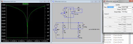
Tuning it may be a challenge with so many elements. I was looking at a bridge circuit that would also work (below, can not remember the name) as long as the source is relatively balanced. Otherwise the common mode of the opamp will be "stressed" if used as shown and probably limit its performance.
Attachments
Demian, in this or another thread you mentioned you were looking at upgrading an ESI Juli@ card. I am waiting for my Juli@ to be delivered, and was wondering how critical the link between the interface part and the analog part is.
IOW, would it be an option to remote the analog board with an (auto)ranger in an external box with a flatcable connection? If necessary a screened flatcable?
Any thoughts on that?
Jan
IOW, would it be an option to remote the analog board with an (auto)ranger in an external box with a flatcable connection? If necessary a screened flatcable?
Any thoughts on that?
Jan
@Chris719 -- I don't know of a diff circuit, I'm basically a single-ended kind of guy. Common mode troubles with op amps make all sorts of horrible distortion, which is why Viktor used all ground referenced amps in his oscillator.
@Demian -- I'm going to have to simulate that variant of the Wien bridge to see what the equal R values force the system into -- my mental scope doesn't see what's going to happen.
In my fooling around with modding an HP 334 THD Analyzer's bridge amp, I just could not get the Wien bridge circuit to work without producing second H. spikes when the bridge fed a diff amp to sum a notch with feedback for higher Q.
Hi:
The thermistor (or incandescent lamp of HP, circa 1939) is the best engineering solution and simpler by far. The opamps will add distortion. See the late (and great!) Jim Williams app notes in EDN and Linear Technology for a very long essay on lowest THD wide range audio oscillators.
Finally suggest to compare to TEK SG505, a Tektronix TM 500 plugin, with 22 dbm balanced out and 10 Hz..100 kHz range.
Enjoy,
Jon
Linear Tech Oscillators
It looks like the above pages 62-65 was for 10k sine wave. Has anyone built one and compared it to Viktor's?
Also, has anyone tried Linear's variable Super Low Distortion oscillator?
Solutions - Super Low Distortion Variable Sine Wave Oscillator
In a controlled system like an oscillator you can be more successful. The composite amp in the LTC super oscillator http://cds.linear.com/docs/en/application-note/an67f.pdf pg. 62 is a good example. It is also clear that making it work across a broader band is difficult. I am really interested in Samuel's execution.
For a general purpose amplifier getting a composite to behave well is very challenging.
It looks like the above pages 62-65 was for 10k sine wave. Has anyone built one and compared it to Viktor's?
Also, has anyone tried Linear's variable Super Low Distortion oscillator?
Solutions - Super Low Distortion Variable Sine Wave Oscillator
I realize this is very long thread however if you read the thread you will find an answer to your questions and suggestion. Everything on low distortion oscillators has been discussed to ad nauseam tested and verified. Victor's oscillator is simply the best fixed frequency oscillator and I have a design of my own which is variable. Others have done the same with comparable results all which surpass the vintage designs.
@Demian -- I'm going to have to simulate that variant of the Wien bridge to see what the equal R values force the system into -- my mental scope doesn't see what's going to happen.
I had similar questions so here is a quick simulation. It actually works quite well. The simulation shows a 100 dB notch with no feedback. However if the signal is not perfectly balanced it seems to degrade. I'm sure there is something I overlooked. This is not a real test but shows it can work.
Attachments
Demian, in this or another thread you mentioned you were looking at upgrading an ESI Juli@ card. I am waiting for my Juli@ to be delivered, and was wondering how critical the link between the interface part and the analog part is.
IOW, would it be an option to remote the analog board with an (auto)ranger in an external box with a flatcable connection? If necessary a screened flatcable?
Any thoughts on that?
Jan
You can remote via the I2S interface pretty easily. You could connect it to any of a number of possible hardware options. I have figured out the interface pretty completely. I'll post it when i find my notes in a fresh thread.
I also just figured out how to upgrade the opamps, which are in an odd package. It seems the VSSOP package might work. Its narrower so not real easy but possible. TI has some good options in that package.
I realize this is very long thread however if you read the thread you will find an answer to your questions and suggestion. Everything on low distortion oscillators has been discussed to ad nauseam tested and verified. Victor's oscillator is simply the best fixed frequency oscillator and I have a design of my own which is variable. Others have done the same with comparable results all which surpass the vintage designs.
Hi -- I am out of Nepal and back in Bangkok...... how is your excellent osc design progressing..... ?
-THx-RNMarsh
Hi -- I am out of Nepal and back in Bangkok...... how is your excellent osc design progressing..... ?
-THx-RNMarsh
Hi Rickard,
It was an intense endeavour putting all that together. Been taking a bit of a break from it and pondering on what to do for a post amplifier. Quite changeling to come up with an amplifier that can keep up with the oscillator. Also the day job gets in the way. Not much poop left at the end of the day.
I have a week of holidays next week. I'll work on an enclosure for it so I can send it down to you for testing when you get back.
- Home
- Design & Build
- Equipment & Tools
- Low-distortion Audio-range Oscillator