
Richard -- want to fill us in with the parameters you were using in the DSP analyzer panel?
Please see Samual Groner. I was given the info by SG at:
www.sg-acoustics.ch/forum/FFT.png.
-RM
Last edited:
SVO Ver 2 board.
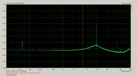
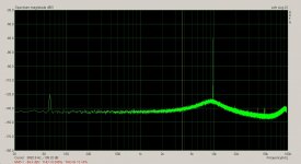
I've got VER 2 of my SVO up and running on the new board. The biggest improvement is with the AGC. It's working very well indeed. Below is a couple of screen shots both at 10kHz in the upper range. The caps are mica 330pF. The first pic is with the caps unshielded and the second is with the caps wrapped in aluminum foil and grounded.
I'll be wrapping the caps in copper foil and grounding them.
Attachments
Last edited:
Hi David,
Nice to hear of your results.
I assume the caps are through hole CDE silver mica? Do you use all/mix of THT comps for the pcb?)
If you were to have used the SM versions, would you expect diff results? You could probably bridge a SM cap across the cap PTH's to see how they perform. At least a NPO grade SM cap. CDE makes silver mica SM caps as well. Hope you have some on hand, don't mean to have to place another Mouser/DK order")
Cheers
Rick
Nice to hear of your results.
I assume the caps are through hole CDE silver mica? Do you use all/mix of THT comps for the pcb?)
If you were to have used the SM versions, would you expect diff results? You could probably bridge a SM cap across the cap PTH's to see how they perform. At least a NPO grade SM cap. CDE makes silver mica SM caps as well. Hope you have some on hand, don't mean to have to place another Mouser/DK order
Cheers
Rick
Hi Rick,
All the caps are Panasonic polypropylene except for the highest range which are silver mica.
They are all very large and tend to act as antennas. Wrapping them helped but the end result was not as quite good as the shot I put up here, Surface mount would probably be better because of the lower profile. But this will have to be for another PCB. This one is for bent wire. The IC's area all SMT SIOC.
I'm not trusting the results from the EMU0204. The sound cards are very sensitive at these low levels. With out an input conditioner the 0204 picks all the surrounding noise.
It's hard to tell the oscillator disto from the noise. It will help having the board in a chassis.
At the moment in it's sitting on a grounded hunk of copper clad.
Cheers,
Hi David,
Nice to hear of your results.
I assume the caps are through hole CDE silver mica? Do you use all/mix of THT comps for the pcb?)
If you were to have used the SM versions, would you expect diff results? You could probably bridge a SM cap across the cap PTH's to see how they perform. At least a NPO grade SM cap. CDE makes silver mica SM caps as well. Hope you have some on hand, don't mean to have to place another Mouser/DK order
Cheers
Rick
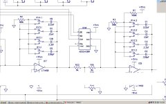
Here is snippet from the schematic for the SVO.
I tried Bruce Hoffer's trick of charging the caps that are not in use.
The caps are charges to a quadrature relationship. The BP section caps are near ground and the LP section caps are charged with a DC voltage equal to the peak level value. When the caps are switched in they are primed and ready to go. This minimizes the work the AGC must do during a range change.The result is less settling time when switching between ranges.
Attachments
When ready, ship it to me to test on AP for you... We are both on the Left coast so i can do fast and get it back to you same week. It will verify for you anything the 0204 showed.
-Richard
I have to do a PCB for uP controller. This will have ground isolation from the SVO board.
The isolation is must. There is way too much hash noise from the uP as it is. It takes about a month to get a PCB to where I am. Then I have to box the whole thing up. Enclosures seem to be the hardest part. Lots of stock out there but all the wrong size.
Do you have quiet bench supplies +/-15?
I'll ship it down to you. You keep as long as you want.
Check your mail again I sent those app files.
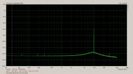
This is with a sheet of grounded aluminum foil over the SVO board.
All else the same.
I guess I can live with this. I'd rather see the disco into the noise floor but it is 10kHz.
Rick I think I'm just going to build an enclosure out of FR4 for the time being. Since I'm not making boards anymore I have to do something with all the copper clad I have laying around.
Compared to the cost of aluminum enclosures these days the copper clad is probably cheaper.
If I had a source for aluminum mill stock here some aluminum bar with plate on the top and bottom would do. Just screw it all together. I'm getting tier of living in a small town. Cookie tins are starting to look appealing.
Cheer,
Attachments
I have to do a PCB for uP controller. This will have ground isolation from the SVO board.
The isolation is must. There is way too much hash noise from the uP as it is. It takes about a month to get a PCB to where I am. Then I have to box the whole thing up. Enclosures seem to be the hardest part. Lots of stock out there but all the wrong size.
Do you have quiet bench supplies +/-15?
I'll ship it down to you. You keep as long as you want.
Check your mail again I sent those app files.
Ok. yes, I have plenty of quiet power supplies to use.
-Richard
Ok. yes, I have plenty of quiet power supplies to use.
-Richard
That's all it going to need. What you've seen so far is powered from a crappy nothing special bench supply. I haven't tried the ultra quiet SVO power supply yet.
davada,
I sent you a message via email to your question. Sorry for the delay.
Dave
Must be in Gmail. I don't see it in my ISO account.
Here is snippet from the schematic for the SVO.
I tried Bruce Hoffer's trick of charging the caps that are not in use.
The caps are charges to a quadrature relationship. The BP section caps are near ground and the LP section caps are charged with a DC voltage equal to the peak level value. When the caps are switched in they are primed and ready to go. This minimizes the work the AGC must do during a range change.The result is less settling time when switching between ranges.
This is a neat idea. I charged the unused agc filter capacitors in my THD analyzer, but never thought of this technique for the SVO.
The technique analogous to this for L-C oscillators was used in the oscillators of Touch-Tone telephones beginning in 1965. It was called "shock excitation". An appropriate amount of current was passed through the inductor of the oscillator, and when the button was pushed, it interrupted the current, causing the oscillator to immediately operate. Touch tone receivers had to operate on tones as brief as a 40ms push of the button. Although the touch tone keypads produced two tones, it was all done with one transistor
.Cheers,
Bob
This is a neat idea. I charged the unused agc filter capacitors in my THD analyzer, but never thought of this technique for the SVO.
The technique analogous to this for L-C oscillators was used in the oscillators of Touch-Tone telephones beginning in 1965. It was called "shock excitation". An appropriate amount of current was passed through the inductor of the oscillator, and when the button was pushed, it interrupted the current, causing the oscillator to immediately operate. Touch tone receivers had to operate on tones as brief as a 40ms push of the button. Although the touch tone keypads produced two tones, it was all done with one transistor
Cheers,
Bob
The closer the voltage across the cap is to the peak of the sine the less time it takes to settle. If you get it spot on there only a small almost undetectable glitch viewing on an oscope when changing range. This is at the lowest frequency. With 324k source resistor it takes a while to reach full charge. One can't be switching back and forth at a fast rate.
- Home
- Design & Build
- Equipment & Tools
- Low-distortion Audio-range Oscillator