What do you use for stimulus when doing the transformer test to find C shunt?
I use a 1000 ohm resistor in series with the transformer secondary. It is shunted by a 500 ohm minimum load resistor. (Which has little effect other than to drop the test voltage.)
I have a capacitor box that switches in different capacitor values. The results are as shown. I source 1 volt and 0 db is 1 volt.
Now if somebody wants to tell me what I've really got here i am interested.
Attachments
Did you short one primary together and short opposing secondary together, and then measure the resulting capacitance? What about putting the primaries and secondaries in series first, then doing the same measurement? You'll also want the secondary leakage inductance to help calculate the snubbers (you probably know this).
This was just looking at the isolation between primary and secondary. Nothing about optimization. I'll get the part number on the transformer and post it this evening.
My success with the most primitive of power supplies suggests that there may be more return in other optimizations- if 200 mV of ripple accounts for less than -130 dB of hum at the output getting zero ripple may be less important. Of course the power supply rejection will follow the open loop gain.
Here
Don't know how the second image got screwed up, but you get the idea.
I have room on the board for two bridges. It's a small change to the layout. The RF filter components are small enough and easily fit. But I don't have room for RC mains filtering unless I enlarge the board. Peltier cooler might be a bit extreme.
These transformers put out about a 5% clipped sine which might complicate the spectrum analysis you described.
"The diodes only conduct when current flows, so you get as much as 10 db lower line noise"
Then the ground is floating most of the time. Interesting.
S7000 - finally a correct grounding scheme keeping all grounds (ie; current loops) isolated and separate till the latest possible point in circuit. A lot of
people either a) don't get it b) don't want to spend the extra money on it.
Z
I assume mains filtering means something on the primary side, that's not needed. RCs on the secondary are fine. I assume you looked at my schematic and noted how the out of phase secondaries help even more.
If I get a chance tomorrow I will post transformer distortion plots. They all distort!
All mains has lot's of H3 symmetrical distortion with a typical 'flat top', however I don't see this as a massive problem.
The biggest issue I have found is a transient-like energy spike on the returning
wave on transformer secondary. It seems this may be either running the core
'too hard', leakage inductance or a combination of both.
I recently did a valve amp repair where an impervious mains related noise was
present in the amp. After much frustration I tracked it down to heater supply
wave form spikes. No amount of snubbing would get rid of this due to the
very high current / low impedance nature of the HTR winding.
Connecting another transformer for heaters only cured the noise.
I'm wondering if the proliferation of Chinese transformers, read cheap core
steel is a factor here.
Z
Here in USA all mains do not all have flat topped waveforms.... only if the transformers are heavily loaded (over loaded)/saturated.
Transformer VA Ratings are a great spec to cheat.... Price competition is very high.... more VA/$ is the issue for sales. Here, we go by a set temperature rise to rate VA. A good company will tell you the temp at which they rate VA. To cut costs, the core material and wire size are often reduced without changing the VA spec they give. Better to buy 2 X VA to get the VA you want if buying cheap transformers.... especially if there is no temp rating or standards referred to in their rating.
Thx-RNMarsh
Last edited:
This was just looking at the isolation between primary and secondary. Nothing about optimization. I'll get the part number on the transformer and post it this evening.
My success with the most primitive of power supplies suggests that there may be more return in other optimizations- if 200 mV of ripple accounts for less than -130 dB of hum at the output getting zero ripple may be less important. Of course the power supply rejection will follow the open loop gain.
Try the same with an integrator. The ripple gets in other ways. Not necessarily directly through the power pins.
Also load the rails so there a more significant amount of current in the rails.
Last edited:
Here in USA all mains do not all have flat topped waveforms.... only if the transformers are heavily loaded (over loaded)/saturated.
Transformer VA Ratings are a great spec to cheat.... Price competition is very high.... more VA/$ is the issue for sales. Here, we go by a set temperature rise to rate VA. A good company will tell you the temp at which they rate VA. To cut costs, the core material and wire size are often reduced without changing the VA spec they give. Better to buy 2 X VA to get the VA you want if buying cheap transformers.... especially if there is no temp rating or standards referred to in their rating.
Thx-RNMarsh
So your saying avoid Chinese transformers?
So your saying avoid Chinese transformers?
Avoid specs and price that don't match.
-RNM
just buying a higher VA xfmr off the shelf doesn't necessarily solve buzzing - thats related to B which is only helped by getting a larger core and asking for a different winding - to a lower operating B
an off the shelf option for the US is to use a "universal" dual primary wired in series for 240 at 120 V to halve the B (and the effective VA re the nameplate #)
an off the shelf option for the US is to use a "universal" dual primary wired in series for 240 at 120 V to halve the B (and the effective VA re the nameplate #)
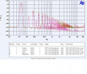
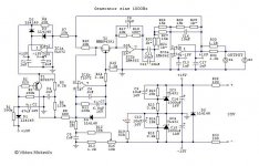
Attached is the distortion of a Signal Transformer EI core unit. The AC line source was my Audio Precision driving an Ashly Audio power amplifier. The input distortion level is below .5% as driven.
Note that most transformers are rated for 110 volts!
I do agree using a transformer that is rated for more power than is required is good practice. However the changes that are created by that are not all to the better.
As the distortion from the transformer is just about the same as is produced by rectification, there is not much advantage in having lower distortion. Your filter should get both forms of distortion.
Now Power Supply Rejection Ratio is a different issue. For a simple opamp circuit the PSSR is almost always degraded by input impedance differences. Those differences degrade the Common Mode Rejection Ratio and that shows up as less PSSR.
Now using a simple regulator chip to clean up the power supply helps but the PSSR of the chips I have tested fall off at the frequencies where hearing is most critical.
Attachments
Sorry to be on-topic
Worked a bit on the Boonton this afternoon. Put in some tweaks I picked up from Demian.
One additional one: the Boonton 1130 has a balanced input implemented as two BNCs named 'High' and 'Low'. The balanced input mode is enabled with the 'Float' button, else the Low input is internally grounded by a relay.
So far so good, but grounded to what?
Well I got an immediate 8dB gain in thd by setting the input to float and terminating the Low input with a 50ohm terminator.
So the internal ground for the shorting switch is not so clean as expected.
Onward...
Jan
Sorry to be on-topic
Worked a bit on the Boonton this afternoon. Put in some tweaks I picked up from Demian.
One additional one: the Boonton 1130 has a balanced input implemented as two BNCs named 'High' and 'Low'. The balanced input mode is enabled with the 'Float' button, else the Low input is internally grounded by a relay.
So far so good, but grounded to what?
Jan
We'll have to refresh Demian's memory -- I seem to recall that if you connect the 'High' of the generator to the 'Low' of the analyzer (and vice versa) you knock down the THD%.
My Boonton 1120 went to EBay, and it fetched a nice price. I do recall that the output amplifier on early 1120's was just based on NE5534's from an early manual, but the one i had used MJE15030/1. I measured it out of the box with the AP and powered by batteries and the distortion was quite low. I think you could do it one better by using Dick Marsh's headphone amplifier circuit if you can find a spare copy of Linear Audio lying around.
if you can find a spare copy of Linear Audio lying around.
Actually the Boonton 1130 is an analyzer-only. I'm using a Victor 1kHz generator.
BTW Does anyone have a circuit diagram for that generator that includes the output level control?
Yeah I know, I can reverse engineer the board...
Jan
Actually the Boonton 1130 is an analyzer-only. I'm using a Victor 1kHz generator.
BTW Does anyone have a circuit diagram for that generator that includes the output level control?
Yeah I know, I can reverse engineer the board...
Jan
Isn't the volume control the AGC level set?
I have a schematic here but I'm not sure if this is Viktor's original or someone else's art.
Attachments
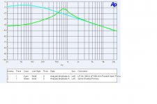
I use a 1000 ohm resistor in series with the transformer secondary. It is shunted by a 500 ohm minimum load resistor. (Which has little effect other than to drop the test voltage.)
I have a capacitor box that switches in different capacitor values. The results are as shown. I source 1 volt and 0 db is 1 volt.
Now if somebody wants to tell me what I've really got here i am interested.
An LC resonance.
Thx-RNMarsh
I think the problem with sizing most transformers is the fact that people think if they take the DC current value they need they just can go find a transformer rated at the same value they will be good. I found a 1.8 factor is a good rule of thumb. Is the 2x you guys mention above and beyond this consideration?
Also people don't understand how temperature rise comes into play, as stated above.
Also people don't understand how temperature rise comes into play, as stated above.
Is the 2x you guys mention above and beyond this consideration?
Also people don't understand how temperature rise comes into play, as stated above.
re 2X. No, it is just a rule from my own thumb of experience with sourcing cheap transformers.
The transformer temp rise is from the loaded secondary causing IR and core losses to create the rising temperature... the materials used in construction... insulations and bobbin materials and the like have a safe temp rating as well. All factored in, the transformer ratings are based on this loaded effect on temp and the deteriouration of insulation with temp rise et al expressed with the VA rating. Best to adhere to the standards about such things and ask to see what standard they go by and guarantee their spec to that standard. Good luck with finding that with cheap transformers.
-RM
Last edited:
- Home
- Design & Build
- Equipment & Tools
- Low-distortion Audio-range Oscillator