Here
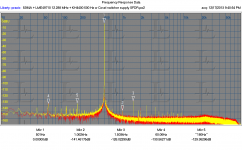
Don't know how the second image got screwed up, but you get the idea.
That's pretty significant. Where do see the most gain from? RC mains filtering, RF filtering shunts, winding separation (dual bridge)? If you were to categorize.
I assume mains filtering means something on the primary side, that's not needed. RCs on the secondary are fine. I assume you looked at my schematic and noted how the out of phase secondaries help even more.
If I get a chance tomorrow I will post transformer distortion plots. They all distort!
If I get a chance tomorrow I will post transformer distortion plots. They all distort!
That's pretty significant. Where do see the most gain from? RC mains filtering, RF filtering shunts, winding separation (dual bridge)? If you were to categorize.
Dual bridge is 10-20 dB. RC is 5 dB. Bypasses affect radiated noise and that depends on the rest of the design. Out of phase windings are 10-20 but above 10khz.
I assume mains filtering means something on the primary side, that's not needed. RCs on the secondary are fine. I assume you looked at my schematic and noted how the out of phase secondaries help even more.
If I get a chance tomorrow I will post transformer distortion plots. They all distort!
No I mean the RC reservoir cap banks.
These transformer are so called Humbucking wound. I think what Signal transformers mean by this is one bobbin is flipped over from the other so the magnetic fields are opposing.
What would be the effect if any of reversing the winding on one of the two bridged with transformer arrangement?
Attachments
I do the same thing -- two separate power supplies -- one for each polarity. Two transformers and two rect etc. Reverse phase on one of the secondary windings. The use of 2 transformers results in better isolation. I also use transformers which do not overlap their pri-sec winding on top of one another. .... more isolation. A ferrite and 1-2mfd on the paralleled primaries is a good beginning. I don't do any regulation/C-multiplier until inside the amp. The transformers and rect and filters are in a remote metal box. This keeps the Xfmr fields away from amp circuits without the need for extreme shielding techniques.... just simple distance atten.
Thx-RNMarsh
Thx-RNMarsh
I do the same thing -- two separate power supplies -- one for each polarity. Two transformers and two rect etc. Reverse phase on one of the secondary windings. The use of 2 transformers results in better isolation. I also use transformers which do not overlap their pri-sec winding on top of one another. .... more isolation. A ferrite and 1-2mfd on the paralleled primaries is a good beginning. I don't do any regulation/C-multiplier until inside the amp. The transformers and rect and filters are in a remote metal box. This keeps the Xfmr fields away from amp circuits without the need for extreme shielding techniques.... just simple distance atten.
Thx-RNMarsh
The transformers I'm using have four separate windings. Two primary and two secondary.
This supply is intended to be in it's own enclosure far from the oscillator. The is more RC filtering on the oscillator board. All the rails are RC filtered. The noisy rails have simple shunt regulation to isolate currents from the oscillator core. Pruning can come later.
The really noisy stuff is on it own isolated power supply. Seems a bit overkill but like I said it can be pruned late. Better not to be caught short.
The transformers I'm using have four separate windings. Two primary and two secondary.
......... Seems a bit overkill but like I said it can be pruned late. Better not to be caught short.
They may be separate windings --- BUT the transformers I use do not have the primary and secondary wound on top of each other. How about yours? Mine are side by side windings. This gives extremely low winding to winding capacitance.
Thx-RNMarsh
They may be separate windings --- BUT the transformers I use do not have the primary and secondary wound on top of each other. How about yours? Mine are side by side windings. This gives extremely low winding to winding capacitance.
Thx-RNMarsh
I think you mean the two primaries are not stacked one on top of the other. Is this correct?
These transformer primaries are on separate bobbins and placed side by side at opposite ends of the core. Take a look at the PDF I attached a few posts ago.
This is the transformer in question: http://www.signaltransformer.com/sites/all/pdf/LP.pdf It has pretty good isolation between primary and secondary. Unfortunately the adjcent winding are primary and secondary so there is more capacitive coupling that ideally possible. They do work pretty well. You must have the primarys in the correct phase for them to work. You can wore the secondarys out of phase but not with a shared bridge.
There are two noise modes to deal with. The normal mode (noise between line and neutral) that the machinations around the supplies help and common mode noise where the noise is coming in via the power cord and leaving some other way. The common mode is more insidious since you can't easily insert a high impedance in series with it. The best you can do would be a shunt path (e.g. transformer shield) back to the noise source, a low cap transformer like the signal above or a major piece of common mode iron/ferrite. The noise sources are higher impedance so they don't easily attenuate with ferrites. I would content that this issue is more important and affects audio systems more than normal mode noise or ripple on transformers.
There are two noise modes to deal with. The normal mode (noise between line and neutral) that the machinations around the supplies help and common mode noise where the noise is coming in via the power cord and leaving some other way. The common mode is more insidious since you can't easily insert a high impedance in series with it. The best you can do would be a shunt path (e.g. transformer shield) back to the noise source, a low cap transformer like the signal above or a major piece of common mode iron/ferrite. The noise sources are higher impedance so they don't easily attenuate with ferrites. I would content that this issue is more important and affects audio systems more than normal mode noise or ripple on transformers.
This is the transformer in question: http://www.signaltransformer.com/sites/all/pdf/LP.pdf It has pretty good isolation between primary and secondary. Unfortunately the adjcent winding are primary and secondary so there is more capacitive coupling that ideally possible. They do work pretty well. You must have the primarys in the correct phase for them to work. You can wore the secondarys out of phase but not with a shared bridge.
There are two noise modes to deal with. The normal mode (noise between line and neutral) that the machinations around the supplies help and common mode noise where the noise is coming in via the power cord and leaving some other way. The common mode is more insidious since you can't easily insert a high impedance in series with it. The best you can do would be a shunt path (e.g. transformer shield) back to the noise source, a low cap transformer like the signal above or a major piece of common mode iron/ferrite. The noise sources are higher impedance so they don't easily attenuate with ferrites. I would content that this issue is more important and affects audio systems more than normal mode noise or ripple on transformers.
Demain have you used any of the common mode choke transformers either before or after
the bridge. I wonder how effective they are. There are some small common mode toroid available at a reasonable price.
I would think a common mode choke which has one coil on the positive leg and one on the negative leg would be most effective, not one per bridge. (This might not be clear, but two bridges as above and then after the first capacitor after the bridge, split across the two halves of the circuit).. I think I might try a few arrangements and compare..
I have done those tricks but they really are more series inductor filters that common mode filters.
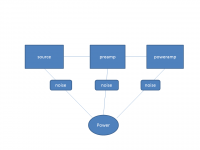
To understand the problem draw a system with a single conductor between each chassis and between each chassis and a common point(the power source). Each box and the power source is capable of generating noise between its chassis and the power connection. The connections between the chassis are the audio/digital links. The more pieces the more complex this mess gets. The noise energy in the power will get conducted through the chassis even if the coupling has a very high impedance. And its a matrix with the energy going everywhere. Unless you can shunt the noise around the sensitive circuitry it will get into it.
The noise source can be modeled as a voltage with a high series impedance. That's why adding a ferrite that may be 300-400 Ohms at 10 MHz won't have a big effect.
The distortion plot shows the difference between a good switching power supply module (Cosel) and a cheap crude linear supply (Jameco JE215: JAMECO KITPRO: Education & Hobby Kits) powering an ADC demo board. There are no onboard regulators for the analog opamps. Even with 200 mV of ripple on the analog supply you don't get more than -130 dB (ref 2V) in the output. I think this underscores how effective the power supply rejection is on decent opamps. Setting up a really clean linear supply did not make a difference. Connecting the chassis together (generator and ADC) in the wrong place makes a mess of it.
Attachments
This is the transformer in question: http://www.signaltransformer.com/sites/all/pdf/LP.pdf It has pretty good isolation between primary and secondary. Unfortunately the adjcent winding are primary and secondary so there is more capacitive coupling that ideally possible. They do work pretty well. You must have the primarys in the correct phase for them to work. You can wore the secondarys out of phase but not with a shared bridge.
Thanks for the link, I'll consider these for my design. Do you have any idea about the coupling capacitance value?
There are two noise modes to deal with. The normal mode (noise between line and neutral) that the machinations around the supplies help and common mode noise where the noise is coming in via the power cord and leaving some other way. The common mode is more insidious since you can't easily insert a high impedance in series with it. The best you can do would be a shunt path (e.g. transformer shield) back to the noise source, a low cap transformer like the signal above or a major piece of common mode iron/ferrite. The noise sources are higher impedance so they don't easily attenuate with ferrites. I would content that this issue is more important and affects audio systems more than normal mode noise or ripple on transformers.
This can't be stressed enough. Differential mode is simply no problem if basic good design practice is followed. On the other hand, common-mode noise is only an issue if the secondary side of the power supply is floating (e.g. in order to give a floating signal output).
Samuel
I measured one of the signal transformers just now. Its around 10 pF from primary to secondary on one leg so the composite is probably twice that. They do buzz a little so not for sensitive home hifi unless buried in heavy casework, but fine for a test instrument. There are several vendors for these and similar transformers including potted examples.
The Triad toroid that ES pointed out elsewhere Triad Magnetics Power Transformers | Mouser works well and doesn't buzz. Bigger and harder to PC mount however.
The Triad toroid that ES pointed out elsewhere Triad Magnetics Power Transformers | Mouser works well and doesn't buzz. Bigger and harder to PC mount however.
Did you short one primary together and short opposing secondary together, and then measure the resulting capacitance? What about putting the primaries and secondaries in series first, then doing the same measurement? You'll also want the secondary leakage inductance to help calculate the snubbers (you probably know this ") ).
).
).
Last edited:
Signal also makes standard EI transformers at higher VA ratings with excellent isolation characteristics.... chassis mount. They have their primary and secondary stacked one on top of the other and placed on the center or "I" portion of the transformer. They work well and have good isolation characteristics. Might also be good here or for preamps when mounted remote from sensitive circuitry.
In either case, if you get one with a bifilar wound dual secondary and create a center-tap on the secondary, you can tie that center-tap back to the neutral line (USA) on the primary for improved rejection.
-RM
In either case, if you get one with a bifilar wound dual secondary and create a center-tap on the secondary, you can tie that center-tap back to the neutral line (USA) on the primary for improved rejection.
-RM
Last edited:
I measured one of the signal transformers just now. Its around 10 pF from primary to secondary on one leg so the composite is probably twice that. They do buzz a little so not for sensitive home hifi unless buried in heavy casework, but fine for a test instrument. There are several vendors for these and similar transformers including potted examples.
Thanks, which VA size is your sample?
Samuel
- Home
- Design & Build
- Equipment & Tools
- Low-distortion Audio-range Oscillator