Sam -- the 339A THD (1KHz/.7v) via the 725D. THD (first 5 harmonics) = .000125%
PS -- the A-P THD+N quoted (.0003_%) was via A-P's analog analyzer.
THx - RNMarsh
Last edited:
.000125% of .7 volts would be 8.75 uV The first 5 harmonics would require a bandwidth of at least 5000 hertz. The noise voltage from a 600 ohm resistor at room temperature over a bandwidth of 10,000 hertz would be around 320 nV. So a simple test of using a 600 ohm resistor as the source and seeing what "distortion" is measure would be interesting. Also a check by using a resistive attenuator to lower both the level and the source impedance would be a good double check.
Its a little misleading to compare the "THD" only measurement of the 725D to an AP's THD+N measurement. The 725D samples and effectively measures only the energy at the harmonics in the harmonic analysis mode (see the pictures). It ignores the noise. It would probably read about the same as the AP when measuring the same way. On an AP measuring at such low levels the measurement noise floor is probably limited by the input devices and input attenuator/protection circuits. I believe that the lower limit on a AP2722 is around -115 dB THD+N in whatever the minimum bandwidth is. The 725D's input noise is around 5 nV/rtHz. Measurements in the area below -100 dB are nice but not really useful unless you are preparing marketing material. You need to look at the real harmonic distribution to see what is actually happening. The importance of any of this stuff below -100 dB is a separate and somewhat philosophical discussion.
Very low THD -
Not misleading if you state one is THD and the other is THD+N. Yes, they are comparable and to illustrate the very low distortion level shown by each measuring instrument....which is why I put them both up.
I am interested in what the limits are with test equipment and their accuracy near those limits. Then, I know what is real and what isn't when testing low level distortion.
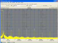
Here is another view of the data with a 339A source and A-P 2722 and a notch of 60dB via B&K 1607 in 'active' notch filter mode. Even more accurate, of course, but still showing well under -130dB for 2H and 3H. Guess I found the answer to the source of the high 3H. This has got to be near the AP's 24 bit limit. The 725 can go lower with accuracy but can not do IM and mulit-tone et al that the A-P can.
Thx-RNMarsh
The blue data is just a calib level of 1 volt, the yellow data is the measurement;

Its a little misleading to compare the "THD" only measurement of the 725D to an AP's THD+N measurement. ----- It would probably read about the same as the AP when measuring the same way.
Measurements in the area below -100 dB are nice but not really useful unless you are preparing marketing material. You need to look at the real harmonic distribution to see what is actually happening. The importance of any of this stuff below -100 dB is a separate and somewhat philosophical discussion.
Not misleading if you state one is THD and the other is THD+N. Yes, they are comparable and to illustrate the very low distortion level shown by each measuring instrument....which is why I put them both up.
I am interested in what the limits are with test equipment and their accuracy near those limits. Then, I know what is real and what isn't when testing low level distortion.
Here is another view of the data with a 339A source and A-P 2722 and a notch of 60dB via B&K 1607 in 'active' notch filter mode. Even more accurate, of course, but still showing well under -130dB for 2H and 3H. Guess I found the answer to the source of the high 3H. This has got to be near the AP's 24 bit limit. The 725 can go lower with accuracy but can not do IM and mulit-tone et al that the A-P can.
Thx-RNMarsh
The blue data is just a calib level of 1 volt, the yellow data is the measurement;
Last edited:
The test was primarily redone with just averaging applied to drop the noise from the graph. The 2722 system setup is as A-P tech support advised...
I don't know what question you asked the tech support so can't tell whether they gave you the correct answer (they didn't the one time I asked them something; since them I'm just communicating with Bruce Hofer), but I can tell you that this is not the sound way to measure the harmonic spectrum of a sinusoidal source.
BTW--that reminds me of an article I read today--Jim Williams a few years back did a "microprocessor corrected ADC" which was accurate to 1 ppm. I'd like to see something like that done here at DIYAudio Land. I wonder if A-P doesn't do something similar.
If you're referring to the same article as I now recall that's at DC where linearity is relatively easy to model and correct (and there are much better ADCs out there--sub 0.1 ppm linearity). At audio frequencies things are quite different.
No I' referring to a more resent post on the progress of your project. You mentioned composite design for the oscillator.
Working very well!
Samuel
I don't know what question you asked the tech support so can't tell whether they gave you the correct answer (they didn't the one time I asked them something; since them I'm just communicating with Bruce Hofer), but I can tell you that this is not the sound way to measure the harmonic spectrum of a sinusoidal source.
If you're referring to the same article as I now recall that's at DC where linearity is relatively easy to model and correct (and there are much better ADCs out there--sub 0.1 ppm linearity). At audio frequencies things are quite different.
Working very well!
Samuel
Excellent.
What I like about the ADC of A-P is it is clean down to the noise floor. Unlike many sound card style products. No artifacts and spurious frequencies displayed and relatively no grounding issues.... though even with the new, cleaner, quieter PS used by PC at this level I also run on pure battery power.
Well,I don't want to bother Bruce Hofer.... as I am not doing a serious product development project - and I have no idea how to import the files you sent me... a description of the setup with A-P tech over the phone worked - sort of. If you can just give me a screen dump picture of the settings for Max resolution and accuracy, I'll manually copy them into a file/setting. I don't have the time luxury to learn the A-P op system for a few tests done every once in awhile. So, I do need some hand-holding on set-up.
Add the fact this PC like most new ones is WIN 8 and A-P doesn't recommend their product with WIN 8 at this time -- so it isn't all 100% easy going. Device driver issues and the likes to solve. Its a miracle this even works at all... never mind perfectly. I'm looking for P-n-P operation kind of help. Got Help in a form factor I can handle?
Thx-RNMarsh
Last edited:
If you're referring to the same article as I now recall that's at DC where linearity is relatively easy to model and correct (and there are much better ADCs out there--sub 0.1 ppm linearity). At audio frequencies things are quite different.
With the computing power we have available --- hard to do is easier to do. A correction to just 1st or maybe 2nd order would help. Point me to the much better ADC and I'll buy it.... I would rather spend more money than more time... so software etc has to be there as well. Turn-key. If it isn't turn-key, then they get bragging rights for technology but I aint interested.
-THx-RNMarsh
Last edited:
but I can tell you that this is not the sound way to measure the harmonic spectrum of a sinusoidal source.
Samuel
I know - quick and dirty to see what was there...... how about the set-up using the 1607? better? Still don't have A-P set up the way I'd like it to be. But, it seems I need to use the analog thd+n part of the system to get lower levels measured and forget the FFT 24 bit ADC as it is a limiting factor. What do you think?
Obviously to design a great new oscillator, it will have to be measured. Davada is on the west cost of N.America (Canada) so I can test for him IF I get the A-P setup right. Also, can use the 725D which is pretty straight forward. I would be looking for better than -140dB re 1v (to 10KHz or more) from SOTA osc/source generator.
Thx-RNMarsh
Last edited:
Richard:
I see the following-
First you need a PC that the software will work with. The AP seems to be less sensitive to PC noise issues so a desktop may be better. I may be able to assemble a Win XP system for you from leftovers here that could be dedicated to AP support.
Second, you need some help getting it running. If you have either wireless or powerline networking to the PC that is running the AP you could set up UVNC on it and we could arrange either for an AP support person or Samuel (or even me) to get it set up remotely. Its not nearly as difficult as you may think to set up remote access. The networked world really enables a lot of otherwise difficult things.
This really isn't too difficult and getting the AP running correctly seems a very worthwhile goal. You have a lot invested in it. Probably more than I have ever spent on a car. Its too valuable to leave stalled. Programming it is not easy but the packaged routines obviate that and should make it pretty easy to get good utility from the box.
Thanks Demian, I appreciate the offer. This A-P is amazing and with the new IM option I put in it should do anything we might want to explore for quit some time.
Let me figure out the XP PC system and I Will take you up on your offer.") I would prefer a portable PC test system. let me know what you need to do and if you want to come over here to see what I have to start with. Remote control operation also sounds fine to me.
I would prefer a portable PC test system. let me know what you need to do and if you want to come over here to see what I have to start with. Remote control operation also sounds fine to me.
I run a fast Internet (20MB/sec) and can stream HD movies.... so test/operation and up/down loads are fast.
Thx-Richard
Let me figure out the XP PC system and I Will take you up on your offer.
I would prefer a portable PC test system. let me know what you need to do and if you want to come over here to see what I have to start with. Remote control operation also sounds fine to me. I run a fast Internet (20MB/sec) and can stream HD movies.... so test/operation and up/down loads are fast.
Thx-Richard
Last edited:
I have no idea how to import the files you sent me...
I don't have the SYS-2722 next to me, but you can easily open the file from the File menu. File/Open/Test... or something like this.
I see if I can send you a screenshot.
Point me to the much better ADC and I'll buy it...
Fluke 8508A, I recall they showed a typical nonlinearity of 0.02 ppm. But forget it--it has sub-Hz sampling rates, that's just for DC.
How about the set-up using the 1607? Better?
1607?
Samuel
I don't have the SYS-2722 next to me, but you can easily open the file from the File menu. File/Open/Test... or something like this.
I see if I can send you a screenshot.
Fluke 8508A, I recall they showed a typical nonlinearity of 0.02 ppm. But forget it--it has sub-Hz sampling rates, that's just for DC.
1607?
Samuel
I think that's his B&K notch filter.
Interesting reading here;
View attachment FFT & ADC.pdf
I find the accuracy of testing with A-P's FFT/ADC is similar to any other 24 bit system.... inaccurate at high and low voltage levels.
But, it also has ramifications for audio music recording.
Thx - RNMarsh
I find the accuracy of testing with A-P's FFT/ADC is similar to any other 24 bit system.... inaccurate at high and low voltage levels.
But, it also has ramifications for audio music recording.
Thx - RNMarsh
I think there is a missed concept here. The FFT and the digital system is more analogous to an analog meter than the complete analyzer. Like the meter you need to operate the digital system where it works well. A meter is usually specified in percent of full scale so a 1% meter at 10% of full scale is only within 10% of accurate. The same relative issue holds with the digital subsystem. You need the analog external scaling in front of the system to get good information. Like the meter, which is very inaccurate at low levels and overload the digital system has a low and high limit for accuracy. In that sense digital is more accurate than any of the analog recording systems we have. In practice something like the AP's analog front end needs only an 8 bit digitizer to show most of the possible information post notch. I used the first gen 8 bit Picoscope on the output of the AP system one and found no down side, and the upside of having a 50 MHz spectrum analyzer with good software.
There are probably a few tests, the Jtest jitter analysis being the most significant I can think of, where a 20+ bit analyzer is useful. 24 bit digitizers at audio frequencies are still not happening. There are several ways to qualify an ADC. Incremental linearity and absolute linearity are different measures, neither guaranteeing the other. Low distortion does not mean the same as accuracy per the digitizer in an HP3458 or Fluke 8508. Those can measure DC very accurately (for at least a few days after calibration). I'm not sure there is a way to digitized a pure sine wave at 10Hz with one that would allow you to verify its distortion. Usually the higher resolution depends on averaging over time, something that doesn't work with a changing voltage.
There are probably a few tests, the Jtest jitter analysis being the most significant I can think of, where a 20+ bit analyzer is useful. 24 bit digitizers at audio frequencies are still not happening. There are several ways to qualify an ADC. Incremental linearity and absolute linearity are different measures, neither guaranteeing the other. Low distortion does not mean the same as accuracy per the digitizer in an HP3458 or Fluke 8508. Those can measure DC very accurately (for at least a few days after calibration). I'm not sure there is a way to digitized a pure sine wave at 10Hz with one that would allow you to verify its distortion. Usually the higher resolution depends on averaging over time, something that doesn't work with a changing voltage.
Low distortion does not mean the same as accuracy per the digitizer in an HP 3458 or Fluke 8508.
But very low uncertainity implies very good linearity (= low distortion). You can't have very low uncertainity over a wide range of values if linearity is poor. In fact the auto-calibration routines of these instruments rely on excellent linearity of the used converters.
I'm not sure there is a way to digitized a pure sine wave at 10 Hz with one that would allow you to verify its distortion. Usually the higher resolution depends on averaging over time, something that doesn't work with a changing voltage.
Averaging corresponds to low-pass filtering, so there's (not surprisingly) a bandwidth limit. But for sub-audio frequencies, these units can be used for low distortion conversion. See figure 9 on page 45 of this document (1989-04.pdf).
BTW, figure 16 of this document (5991-1266EN.pdf) and figure 8 of this document (2114953_a_w.pdf) show typical DC linearity measurements of the two most well known 8.5 digit DMMs (the 0.02 ppm figure I quoted in my previous post was optimistic). This data could in principle be used to determine distortion performance at very low frequencies.
Samuel
I think I managed to confound the points I was trying to make.
First a 24 bit audio converter can have low distortion without the really high accuracy of a precision 24 bit DC converter.
Second, that averaging is used to improve the accuracy of the precision converter/digitizer in a way that limits ac response.
Third (where I really was not clear) is how to generate a really low distortion very low frequency sine wave. I'm not sure that an RC oscillator can work that well at very low frequencies. Not to mention that the settling times could be measured in minutes or even hours, which would obviate any measurements of distortion until it is settled.
The larger point-that a digital capture system would have the same limitations that the previous measurement tools. Even the Fluke 8508 and the Agilent 3458 have analog preconditioning to optimize the measurement.
Error Terminology -
www.NDT-ED.Org/GeneralResources/ErrorAnalysis/UncertaintyTerms.htm
One place the errors could use some DSP power is to correct/cancel the errors at high level input -- if you can call 1 volt -high level.
I noticed BenchMark uses a scheme to prevent extraneous frequencies from being generated. They increased the upper end of the dynamic range so this sort of thing wouldn't happen with their newest ADC/DAC products.
THx-RNMarsh
Can you post a link to the benchmark stuff? I know they are fan's of async sample rate conversion. Others are less inclined to be so enamored of them.
High level really means close to full scale. The AK5394A seems to have few issues within 3 dB of full scale (see attached image).
High level really means close to full scale. The AK5394A seems to have few issues within 3 dB of full scale (see attached image).
Attachments
- Home
- Design & Build
- Equipment & Tools
- Low-distortion Audio-range Oscillator