I would hope that with the 15/16 connected to the 725 via GPIB that when the oscillator level or freq were changed, the 725 analyzer would respond accordingly. OR is the GPIB there to interface with a PC to control and gather data and Not be connected directly to each other. ??
And, then we have APIB. Why didnt A-P stay with GPIB? Is the APIB a stripped down GPIB or what? I guess the APIB/GPIB was put there for a factory automated test station/system and be a way to connect to other brands (TEK, HP, etc). For low volume use, the APIB/hardware/software doesnt seem worth the effort to use it.
THx-RNMarsh
Why did Microsoft change Java?
I guess they did like the way it was.
It looks as though the Shibasoku uses an analog multiplier as the AGC element. Both the AG15 state variable oscillator and the 590AR Wein bridge seem to use the MC1495L analog multiplier http://www.onsemi.com/pub_link/Collateral/MC1495-D.PDF . The part is socketed so selection is probably a key part of the process. They get exceptional performance with pretty conventional parts.
Several other brands of low distortion osc I have here also use the MC1496G.... such as, the HP-339A.
-RM
Last edited:
A current product that may be better and available is the AD539. In the app note on pg 14 they have a .01% distortion example. That's about 40 dB lower harmonics than the MC1495. If it is a contributor then this should make for substantially less distortion (assuming the control voltage is really clean). The Shibasoku's have a sample and hold circuit for the AGC. I have not decoded it in detail so I don't know if its one stage or two.
I used the MC 1495s in a Sin2 + Cos2 = 1 control loop Oscillator. Apart from requiring many presets the linearity appeared to be as good as the AD534 the I used in the circuit published. I am not convinced that any of the newer multipliers are any better.
I agree and it rather sad they are obsolete. There are still some around but sold in 500 lots.
The 1496 and 1495 are two very different ICs. One is a balance modulator and the other is a four quadrant multiplier. I looked into getting some 1495 but Onsemi is no longer manufacturing them.
This is a good point. The 1496 is a simple but very useful circuit. I used it in two ways in my analyzer. The first, and most obvious, is as a phase detector for the auto-tune circuits.
The second, and a bit less obvious, is as the guts of a voltage-controlled amplifier. This is used for the auto-scaling circuit. It is interesting that the VCA configuration I used has a log linear control characteristic over a large signal range that includes both loss and gain. This VCA is not necessarily a champion when it comes to distortion, but is more than adequate for scaling the residual signal.
Cheers,
Bob
Bob -- The old commercial THD models can be modified at low cost but high labor /tiime and still arent as good all around. The better models are outrageouly expensive. Nothing in between.
Oh, the ADC/FFT is in between. But they really are not accurate under -100dB. Add-on a notch filter. Low cost and very good hobby level performance. Now need to go the last step and complete those systems.... someone (QA400?) to integrate the notch filter into their ADC/FFT package and sell it as a total built test equipment package/option. No added DIY kludges needed.
Victor has solved the low cost, impressive spec for an oscillator source that we have been trying to do here with upgrades etc.
Got update/upgrade for your design coming in our life time (or sooner)? Help is available.
-Richard Marsh
Last edited:
A brief update on where my oscillator design stays. Here's the distortion contribution of the leveling loop (level detector ripple and multiplier), determined by measuring the absolute level of the harmonics at the multiplier output and then setting these numbers in relation to oscillator operating level, multiplier decoupling and low-pass action of the SV ring:
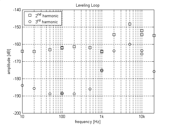
Below 1 kHz, the 2nd harmonic is dominated by the multiplier; above this frequency, level detector ripple becomes significant. This graph does not, of course, consider other distortion sources (in particular amplifiers, passives and layout effects), but I believe that I have reduced these to very low levels too. The complicated measurements with passive notch filters will have to wait, but direct measurement of the oscillator output with the SYS-2722 reveals nothing but the analyzer residual (individual harmonics below -130 dB, THD+N in a 22 kHz BW below -118 dB for most of the audio frequency range).
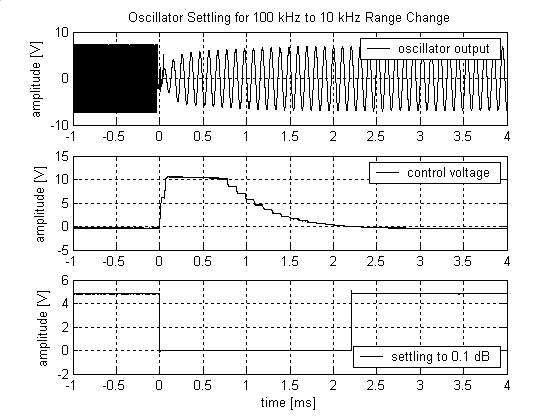
This performance is achieved with excellent settling behaviour. Here's the typical settling for a 100 Hz to 10 Hz range change, which represents the worst-case settling time:

The middle graph shows the multiplier control voltage (i.e. error integrator output), the lower plot the logic output of the circuit which detects amplitude settling to 0.1 dB. Settling for other one-decade-downwards range changes is very similar in behaviour, just scaled inversely to frequency. Here as an example a 100 kHz to 10 kHz case:
Above 10 kHz the step response of the leveling loop changes (for not yet fully clarified reasons), and the settling for a 10 kHz to 100 kHz range change shows a bit of ringing (which however is, as far as I know, of no further consequence):
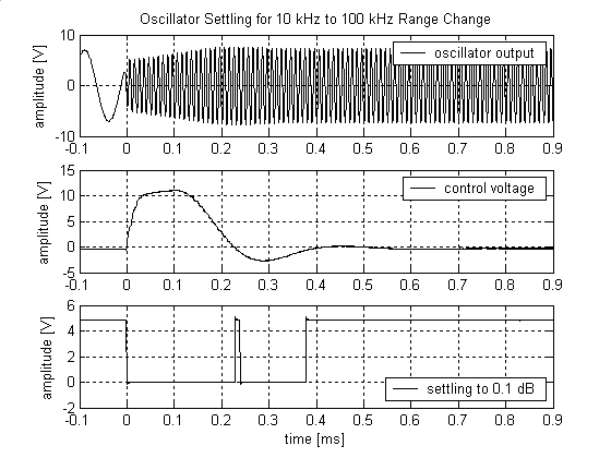
Frequency changes within one range settle extremely fast, and don't even trigger the settling circuitry.
While the circuit complexity of the leveling loop is relatively high, it is composed entirely from cheap standard components (stock Mouser and/or Digi-Key).
Now there's some work left for the output amplifiers and power supply.
Samuel
Below 1 kHz, the 2nd harmonic is dominated by the multiplier; above this frequency, level detector ripple becomes significant. This graph does not, of course, consider other distortion sources (in particular amplifiers, passives and layout effects), but I believe that I have reduced these to very low levels too. The complicated measurements with passive notch filters will have to wait, but direct measurement of the oscillator output with the SYS-2722 reveals nothing but the analyzer residual (individual harmonics below -130 dB, THD+N in a 22 kHz BW below -118 dB for most of the audio frequency range).
This performance is achieved with excellent settling behaviour. Here's the typical settling for a 100 Hz to 10 Hz range change, which represents the worst-case settling time:
The middle graph shows the multiplier control voltage (i.e. error integrator output), the lower plot the logic output of the circuit which detects amplitude settling to 0.1 dB. Settling for other one-decade-downwards range changes is very similar in behaviour, just scaled inversely to frequency. Here as an example a 100 kHz to 10 kHz case:
Above 10 kHz the step response of the leveling loop changes (for not yet fully clarified reasons), and the settling for a 10 kHz to 100 kHz range change shows a bit of ringing (which however is, as far as I know, of no further consequence):
Frequency changes within one range settle extremely fast, and don't even trigger the settling circuitry.
While the circuit complexity of the leveling loop is relatively high, it is composed entirely from cheap standard components (stock Mouser and/or Digi-Key).
Now there's some work left for the output amplifiers and power supply.
Samuel
@Richard Marsh
RE your comment that sound cards and FFT analyzers are not really accurate below -100dB -- I've tested the displayed level accuracy of the EMU 0204 with ARTA, using several precision attenuators, and the levelo accuracy is very good to below -120dB and within 1dB at -140dB -- I think that qualifies as accurate. This depends critically on using extremely fine resolution bandwidth, ie very large sample size, to assure that the spectral bins are narrow enough to capture the peak signal levels and not the surrounding noise.
Granted that the level accuracy is for individual harmonic products, and is not the accuracy of the software's calculated values for THD or THD+N, but it is trivial to do a RSS calculation of the total harmonics for accurate THD.
So I'm thinking you must mean the calculated values for THD+N; if so, the calculated values in ARTA have been very good for me on my version of Bob Cordell's SV oscillator, with results well below -110dB and approaching -120dB -- really, that's not bad -- BUT -- I do not have independent confirmation of those results, and so am taking a lot on trust here. Verification may come from my finishing an auto-tuned active Twin-T notch filter that has been sitting on the floor for months waiting for other things to move out of the way.... I'm also patiently waiting for David's finished oscillator design.
Demain... that is exactly what I see happening as well. And, I think it is coupled with the notch phase response - either hardware or software or both. This needs more flushing out -- but just using the DSP/FFt in the ShibaSoku I get differences of 3dB between them and that is only for the 2H at the -100dB level which is closes to the notch side effects.
I want to believe the ADC/FFT/notch et al is as good as it needs to be and it appears very very good. Some imperfection is OK, of course. Just need verification.... so far it is worrisome a little. But, i live in hope that with all the progress here with source generators and analyzers we will have something great at affordable prices.
SG's is clearly Over-The-Top.") Cant wait to see everyones working ideas turn into something we can make/buy which covers the price gap between budget and breaking the bank account. Its all good stuff!
Cant wait to see everyones working ideas turn into something we can make/buy which covers the price gap between budget and breaking the bank account. Its all good stuff!
Thx-Richard Marsh
I want to believe the ADC/FFT/notch et al is as good as it needs to be and it appears very very good. Some imperfection is OK, of course. Just need verification.... so far it is worrisome a little. But, i live in hope that with all the progress here with source generators and analyzers we will have something great at affordable prices.
SG's is clearly Over-The-Top.
Cant wait to see everyones working ideas turn into something we can make/buy which covers the price gap between budget and breaking the bank account. Its all good stuff!Thx-Richard Marsh
Last edited:
A brief update on where my oscillator design stays. Here's the distortion contribution of the leveling loop (level detector ripple and multiplier), determined by measuring the absolute level of the harmonics at the multiplier output and then setting these numbers in relation to oscillator operating level, multiplier decoupling and low-pass action of the SV ring:
Below 1 kHz, the 2nd harmonic is dominated by the multiplier; above this frequency, level detector ripple becomes significant. This graph does not, of course, consider other distortion sources (in particular amplifiers, passives and layout effects), but I believe that I have reduced these to very low levels too. The complicated measurements with passive notch filters will have to wait, but direct measurement of the oscillator output with the SYS-2722 reveals nothing but the analyzer residual (individual harmonics below -130 dB, THD+N in a 22 kHz BW below -118 dB for most of the audio frequency range).
This performance is achieved with excellent settling behaviour. Here's the typical settling for a 100 Hz to 10 Hz range change, which represents the worst-case settling time:
The middle graph shows the multiplier control voltage (i.e. error integrator output), the lower plot the logic output of the circuit which detects amplitude settling to 0.1 dB. Settling for other one-decade-downwards range changes is very similar in behaviour, just scaled inversely to frequency. Here as an example a 100 kHz to 10 kHz case:
Above 10 kHz the step response of the leveling loop changes (for not yet fully clarified reasons), and the settling for a 10 kHz to 100 kHz range change shows a bit of ringing (which however is, as far as I know, of no further consequence):
Frequency changes within one range settle extremely fast, and don't even trigger the settling circuitry.
While the circuit complexity of the leveling loop is relatively high, it is composed entirely from cheap standard components (stock Mouser and/or Digi-Key).
Now there's some work left for the output amplifiers and power supply.
Samuel
So when do we get a peek at it?
If it were possible to selectively increase harmonics it may be possible to identify the relative contribution of them but when the system harmonics are at -130 dB or more the contributors are just too complex and too low in level to see where the harmonics are coming from.
Fast settling and low distortion are mutually exclusive it seems. The older Krohn Hite low distortion oscillators could keep the amplitude constant in less than a cycle but had significant feed through of the sample pulse for the sample and hold.The Boonton settles very fast as well but also has the feed through of the sample pulse.
Hofer's "feedforward" cancellation of those errors may hold the key to significant improvement of something like the Boonton but at the levels of the super oscillators it will take something more. On the Boonton the second harmonic is about -105 dB, the third and up are at the -130 levels. This gives me some hope for improving it.
A brief update on where my oscillator design stays. Samuel
Thanks for the update Samuel; nice to see progress! Your undertaking is certainly a huge one!
jan
- Home
- Design & Build
- Equipment & Tools
- Low-distortion Audio-range Oscillator