600 ohms is nice when you get into an output attenuator, which every audio generator really needs. The usual ladder attenuator produces a precision 600 ohms output impedance on each step. for the top (max out) step, you put in a 600 ohm series resistor. Now you have a precision 600 ohm output at all attenuator settings, and the generator is flat into any load in terms of what it is putting out at an impedance of 600 ohms. Note that the ladder does not actually load the output buffer with 600 ohms. For an example, see the output attenuator I use in my distortion analyzer's signal source.
Cheers,
Bob
Hi bob, Im sure you remember that it is possible to have 600ohms in as well as out.
I will break this down into manageable segments since its easy to get lost in details. The first step is the low pass filter or integrator. The question is how much distortion would a filter add or remove? Several variables interact: opamp, level, circuit, loading and component values. Accepting that a VCVA will have a distortion problem (common mode issues) and noise (new to me) then I'll start with an integrator. I'll scale the impedance to 600 Ohms for now.
Key question- can a filter have less distortion at its output than the opamp in unity gain at the same level and loading?
Hello, yes it is possible to have lower distortion output than the op amp at unity gain.
Hi bob, Im sure you remember that it is possible to have 600ohms in as well as out.
I jumper the 600 Ohm series R out of the osc... less potential for noise/EMI/RFI pickup for cables. I dont have to test to a spec on 600 Ohms systems. But then I am not marketing test equipment to everyone, either.
-RM
Hi bob, Im sure you remember that it is possible to have 600ohms in as well as out.
Yes, that is right. When a 600 ohm source is terminated in a 600 ohm load, the output amplitude will drop by 6dB from the open-circuit value.
Cheers,
Bob
I jumper the 600 Ohm series R out of the osc... less potential for noise/EMI/RFI pickup for cables. I dont have to test to a spec on 600 Ohms systems. But then I am not marketing test equipment to everyone, either.
-RM
Hi Rick,
It seem it's in order to have both a low output Z and high output Z source as well. Balanced and single ended and quadrature.
Cheers,
One advantage of having a 600 ohm output is it make it easy to sum two or more signal sources by series or parallel connection. This is handy for arranging a multitude of test setups for various tests like IMD, CCIF as well as injection of markers etc.
Neat idea; I never had the guts to try this.
Cheers,
Bob
Hello, yes it is possible to have lower distortion output than the op amp at unity gain.
Tantalizing response. Perhaps you can add more details so I don't chase down blind alleys? Is it because the loop gain increases above/below the filter cutoff or some other mechanism?
Hi Demian,
There is another filter structure you might look at called the Akerberb-Mossberg.
I don't see it much, or at all, around these corners but it may have application here.
The most interesting thing about it is the positive integrator which may or may not have any benefit.
If you Google the name a ton of stuff will come up on it.
The following is a bandpass configuration.
Cheer,
Attachments
Last edited:
This is an analog equivalent of a pulsed integrator PI controller.
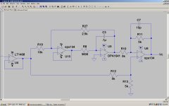
It has the same advantage of self adjusting with frequency like a pulsed integrator but doesn't produce the transients and noise from switching. No timing required. One advantage it has over a switched topology is the exact proportion the integrator changes is controlled by the ratio of R19 and R27. The integrator acts as a servo on it's input signal driving it to zero and outputting the exact amount to the summing amplifier where it's summed with the proportional error. This makes tuning the PI controller simpler because the controller is no longer sensitive to the integrator TC. It can't over shoot which can cause level hunting. The integrator TC can remain fixed and doesn't require changing with oscillator range.
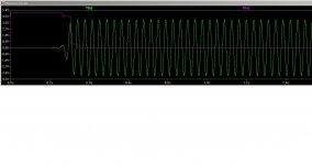
Here is the circuit and a sim of an SVO at about 25Hz. Settling can't be better.
This is a simple form. A second integrator with a shorter TC can be added to handle the servo with it's output driving the PI integrator.
This controller will work equally as well in any AGC loop regardless of rectifying method.
Cheers,
It has the same advantage of self adjusting with frequency like a pulsed integrator but doesn't produce the transients and noise from switching. No timing required. One advantage it has over a switched topology is the exact proportion the integrator changes is controlled by the ratio of R19 and R27. The integrator acts as a servo on it's input signal driving it to zero and outputting the exact amount to the summing amplifier where it's summed with the proportional error. This makes tuning the PI controller simpler because the controller is no longer sensitive to the integrator TC. It can't over shoot which can cause level hunting. The integrator TC can remain fixed and doesn't require changing with oscillator range.
Here is the circuit and a sim of an SVO at about 25Hz. Settling can't be better.
This is a simple form. A second integrator with a shorter TC can be added to handle the servo with it's output driving the PI integrator.
This controller will work equally as well in any AGC loop regardless of rectifying method.
Cheers,
Attachments
Last edited:
Here is the circuit and a sim of an SVO at about 25Hz. Settling can't be better.
This is a simple form. A second integrator with a shorter TC can be added to handle the servo with it's output driving the PI integrator.
This controller will work equally as well in any AGC loop regardless of rectifying method.
Cheers,
Beautiful application with excellent behaviour. Fast even at 25Hz. very nice idea.
Thx-RNMarsh
Beautiful application with excellent behaviour. Fast even at 25Hz. very nice idea.
Thx-RNMarsh
Thanks Rick.
I really did not want to use a pulsed integrator because of the switching noise. At such low levels it shows up in the output of the SVO. But this left a problem of how to tune the integrator TC with frequency change. I came up with a lot more complicated ideas before this. The only reason the integrator is in there is to drive the error to zero. This is a better filter.
Cheers,
Last edited:
David, I'm afraid I don't understand how your controller works - it seems a fixed time constant, low-pass filtered, proportional controller; a gated-gain integrator is actually an integrator whose gain tracks the oscillation frequency, so that the overall ALC loop gain is proportional to oscillation frequency. How a P controller with a little low-pass filtering can replace a gated-gain integrator?
L.
L.
David, I'm afraid I don't understand how your controller works - it seems a fixed time constant, low-pass filtered, proportional controller; a gated-gain integrator is actually an integrator whose gain tracks the oscillation frequency, so that the overall ALC loop gain is proportional to oscillation frequency. How a P controller with a little low-pass filtering can replace a gated-gain integrator?
L.
Hi coluke.
It's one of those post I wish I hadn't put up there. As it is it doesn't work because of the differentiating of the servo. This can be cured by the insertion of two reverse diodes in parallel but the lose through the diodes leaves a large error. Using a second integrator for the servo section enables a shorter TC which give shot of charge to the PI integrator.
To make this work it becomes so complex one may as well just use a pulsed integrator and put a lot of filtering on the power rails to deal with the switching noise. With careful lay out
it can be made to work.
The concept is for an analog solution to the functional equivalent of a pulsed integrator.
Something that will effectively adjust the integrator TC with frequency without getting ridiculously complicated.
At ultra ultra low distortions what I'm finding is distortion is created from AGC functional-component noise and not the oscillator itself. This includes ripple, switching noise and anything that generates harmonic within. This enters the oscillator in combination of direct injection, power rails and strongly by EMI. The best way to deal with this kind of noise is to not generate it in the first place.
I had an ADC set up with time division multiplexing. Since the sample pulse is taken from the oscillator the division of the pulse cause a strong sub harmonic to show up in the oscillator output. It was at -125dB but for an oscillator doing -145dB or better....
I'm convinced by my findings that the distortion from most ultra low distortion oscillators is generated outside the oscillator and at a much greater level than the control element.
One of the advantages of using an high speed ADC for peak detection is it operates well above the bandwidth of interest. The sampling capacitors in ADC are quite small in value and don't generate nearly as much current noise as an analog sampler counterpart.
Let's put our thinking caps on and see if any of us can come up with a solution for a pulsed integrator replacement.
Cheers,
I still like the idea of using an ADC and a DAC with some simple DSP in the middle. Keeping the digits clear of the sensitive path is important but its well understood. The remaining requirement for this is whether the middle is an oscillator or a good low pass filter on the output of a high performance DAC, using the ADC to level the output. It would have the benefit of very low phase noise and very precise frequency. I think this could be done with some not very expensive parts.
My tech has been busy so I have not been able to get to testing filter circuits but hopefully this weekend.
My tech has been busy so I have not been able to get to testing filter circuits but hopefully this weekend.
I still like the idea of using an ADC and a DAC with some simple DSP in the middle. Keeping the digits clear of the sensitive path is important but its well understood. The remaining requirement for this is whether the middle is an oscillator or a good low pass filter on the output of a high performance DAC, using the ADC to level the output. It would have the benefit of very low phase noise and very precise frequency. I think this could be done with some not very expensive parts.
My tech has been busy so I have not been able to get to testing filter circuits but hopefully this weekend.
It would have to be a very fast DSP if it were an oscillator control. But a filter would relax the whole process. Might pursue this at a latter time.
The DSPs I've seen are in unmanageable packages. What do you have for a line up.
I think a lot better when doing a face to face brain storming Q&A session. But will try to brain storm with myself. Talk some more about needs/features and qualifications for a replacement to the pulsed integrator.
Thx-RNMarsh
Hi Rick,
With a micro controller involved a small DAC can replace a switched integrator but I'd like the oscillator to be somewhat independent of the micro. As it is the micro just handles the tuning and this can be replaced with all sort of other tuning methods.
- Home
- Design & Build
- Equipment & Tools
- Low-distortion Audio-range Oscillator