I have a trick for using an LM339 as an active precision rectifier. It has an open collector output and is a linear device inside that recovers from overload really fast so it works well for this. Its "negative logic" so you need to think negative peak capture. You get 4 in a package so its a good match for this. Attached is an illustration of the concept.
However with 4 peaks per cycle you will get ripple at 4X the fundamental. You may also get 2nd and 3rd harmonic modulation if the peak levels of the stages are not identical.
The higher Q will reduce the close in phase noise which is good. But would not the noise floor of 4 opamps summed in effect be higher than 1 or 2? I would think you want the system running at as high a level as possible, but then the nonlinearity of the opamps may become a limit.
Attachments
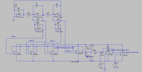
I have a trick for using an LM339 as an active precision rectifier. It has an open collector output and is a linear device inside that recovers from overload really fast so it works well for this. Its "negative logic" so you need to think negative peak capture. You get 4 in a package so its a good match for this. Attached is an illustration of the concept.
However with 4 peaks per cycle you will get ripple at 4X the fundamental. You may also get 2nd and 3rd harmonic modulation if the peak levels of the stages are not identical.
The higher Q will reduce the close in phase noise which is good. But would not the noise floor of 4 opamps summed in effect be higher than 1 or 2? I would think you want the system running at as high a level as possible, but then the nonlinearity of the opamps may become a limit.
I found the LM339 to be quite noisy. Is there another comparator that would work for this. LT has some with light current source pull ups, 100uA. The outputs can be paralleled.
Is it noisy enough to affect the output level significantly in this application? With the integration after the device I would think the noise would not be a major issue. I don't know of another open collector type that is linear to the output and I have looked.
Probably not enough to effect the output level. It's my experience that noise and distortion is transferred to the multiplier through a fast control element and in turn shows up at the output of the oscillator even with large amounts of decoupling.
Whether this is significant or not depends on what we are trying to achieve. If it's a -140 THD or THD+N then yes it matters. With what we have to work with these days the AGC is a dominate source of noise and distortion. Next to that is the multiplier.
Dick, etc.
Just a heads up, the numpy.fft library in Python is arbitrary N so you can always center your tones, runtime suffers for non-factorable sizes but as a research tool it is useful. For instance 192,000 factors way down with 2,3,5 which are all very efficient, but 192,001 might take 30s rather than 80mS. Popular windowing functions are all included also, the book/users manual also has been made a free download.
I don't know if any of the audio related softwares support this.
Last edited:
That sound great, Scott. thx -- I will check it out and see what can be tried and learned from its use.
Each new test ... even with substantially same results often gives up something new. Some little gem or pearl. Or a slightly different view of things or adds greater insights etc.
-RNM
Each new test ... even with substantially same results often gives up something new. Some little gem or pearl. Or a slightly different view of things or adds greater insights etc.
-RNM
Probably not enough to effect the output level. It's my experience that noise and distortion is transferred to the multiplier through a fast control element and in turn shows up at the output of the oscillator even with large amounts of decoupling.
Whether this is significant or not depends on what we are trying to achieve. If it's a -140 THD or THD+N then yes it matters. With what we have to work with these days the AGC is a dominate source of noise and distortion. Next to that is the multiplier.
I think the noise (however much there is) will be attenuated by the integrator and become very small part of the end signal with a passband well below the the frequency of the oscillator. The input offset is approx 1-2 mV which is small in this context. If the noise is a real issue a TH-SH may actually work better if the switching transient can be managed. The through connection for the noise is a very small part of the cycle with the TH-SH solution. It would also avoid the introduction of harmonics from multiple samples per cycle.
I think the noise (however much there is) will be attenuated by the integrator and become very small part of the end signal with a passband well below the the frequency of the oscillator. The input offset is approx 1-2 mV which is small in this context. If the noise is a real issue a TH-SH may actually work better if the switching transient can be managed. The through connection for the noise is a very small part of the cycle with the TH-SH solution. It would also avoid the introduction of harmonics from multiple samples per cycle.
"If the noise is a real issue a TH-SH may actually work better if the switching transient can be managed."
That's a big if. The transients can get into everything. Even using a high performance ADC as a sampler noise and even distortion of the peak get passed through.
I'm not sure of how much, distortion of the peak, contributes to THD.
Excluding a clipped peak of course.
I think the noise (however much there is) will be attenuated by the integrator and become very small part of the end signal with a passband well below the the frequency of the oscillator.
Unfortunately we need a PI controller--the I portion is surely not much of an issue if well designed, but the P portion forwards noise of the detector straight to the multiplier. If there was no need for a P path this thread would proabably not have nearly 300 pages...
Samuel
Interjecting another slightly off the wall idea. IIRC a biquad filter can be configured as a digital oscillator. I don't see, with a little work, why something like miniDSP could not be configured to put out a fundamental and just enough of say the first 5 harmonics in the right gain/phase to cancel the distortion.
You could do a loop through and automate the computations i.e. force the A/D output perfect. Then insert DUT into the path at the same levels. I guess the autmation would require a fully programable DSP.
You could do a loop through and automate the computations i.e. force the A/D output perfect. Then insert DUT into the path at the same levels. I guess the autmation would require a fully programable DSP.
Interjecting another slightly off the wall idea. IIRC a biquad filter can be configured as a digital oscillator. I don't see, with a little work, why something like miniDSP could not be configured to put out a fundamental and just enough of say the first 5 harmonics in the right gain/phase to cancel the distortion.
You could do a loop through and automate the computations i.e. force the A/D output perfect. Then insert DUT into the path at the same levels. I guess the autmation would require a fully programable DSP.
Sounds like a valid approach! Harmonic detection should be easy with a digital PSD, even well below the noise. I think in some cases the distortion of an oscillator is relatively unsteady (e.g. peak level detectors may have slightly different ripple from cycle to cycle)--not sure what effect this would have in such a system.
Samuel
Radiometer CLT-1
BTW, currently for sale a rare component linearity tester: M100214 Radiometer A s Copenhagen CLT1 Component Linearity Test Equipment | eBay
With shipping more than I want to spend, but this would make a good item for RM's collection!")
Samuel
BTW, currently for sale a rare component linearity tester: M100214 Radiometer A s Copenhagen CLT1 Component Linearity Test Equipment | eBay
With shipping more than I want to spend, but this would make a good item for RM's collection!
Samuel
Interjecting another slightly off the wall idea. IIRC a biquad filter can be configured as a digital oscillator. I don't see, with a little work, why something like miniDSP could not be configured to put out a fundamental and just enough of say the first 5 harmonics in the right gain/phase to cancel the distortion.
You could do a loop through and automate the computations i.e. force the A/D output perfect. Then insert DUT into the path at the same levels. I guess the autmation would require a fully programable DSP.
The limit would be lower bit linearity. In theory you would put out a perfect sine. The practice is that the converter is not linear so you get distortion components. Using the same D/A to add a correction signal would have the same error source. A partially adaptive algorithm that looks at the distortion and tries to create a cancellation signal would probably hunt and create all sorts of weird artifacts.
Using a second D/A with much lower maximum level would possibly work better.
The you could also add a third or more chaser to the mix.
ES
Using a second D/A with much lower maximum level would possibly work better.
ES
That was the idea, a modification of what I posted a while ago.
BTW, currently for sale a rare component linearity tester: M100214 Radiometer A s Copenhagen CLT1 Component Linearity Test Equipment | eBay
With shipping more than I want to spend, but this would make a good item for RM's collection!
Samuel
It's a bit pricey for a "parts or not working" offer.
I suspect its all working but they have no idea how to test it. Its a late unit but except for saying RE instead of Radiometer Copenhagen its identical to both of mine. I does have a newer power connector on the back. The shipping price is reasonable, they weigh a ton. The case is aluminium but two layers deep.
It's great for finding bad passives but the good ones are all at the limits of the technology. You may be able to improve it a little(the design is from the late 1960's) but not a lot. The new version is automated but less flexible and no lower a distortion floor. I have the full manual as a PDF to share.
It's great for finding bad passives but the good ones are all at the limits of the technology. You may be able to improve it a little(the design is from the late 1960's) but not a lot. The new version is automated but less flexible and no lower a distortion floor. I have the full manual as a PDF to share.
That was the idea, a modification of what I posted a while ago.
Would it make more sense to use an analog oscillator (no image problems from the DAC) controlled by a DAC, which could feed the "AGC" and any distortion correction signals (and frequency steering) via the same node as a sort of super multiplier. Using an ADC to detect the distortion still would require removing the fundamental since no ADC today is even close to the residual necessary to see just the distortion. If the distortion is primarily from the multiplier an ultra low distortion DAC attenuated by 40 dB might just be as close to perfect as any multiplier will be.
Real question: where is the distortion coming from on these ultra low distortion oscillators? If the multiplier that is one goal. If the amplifiers are limiting it, which they may be, can it get lower? Where is the floor?
That was the idea, a modification of what I posted a while ago.
As soon as you use a second d/a scaled down from the first all you need is an error correction table. It is a technique that could be used to produce more linear higher bit converters.
So you probably could use a fixed error correction table. Wonder why no one makes this as a high accuracy module?
ES
High gnfb via multiple opamps in series is one method to reduce thd and the other, i figured, was to use harmonic cancellation. The first has been tried and with some success.... the second has little work done but offers excellent results if successful methods can be worked out. I think this direction may be fruitful and original work.
Thx-RNMarsh
Thx-RNMarsh
- Home
- Design & Build
- Equipment & Tools
- Low-distortion Audio-range Oscillator