Looks like time for a battery supply. There isn't much else left.
I can help with Praxis. I would need the following info-
1) do you have an Audpod?
2) What OS? 32 or 64?
3) What audio interface are you using?
4) What are the problems you are encountering?
There isn't much for regulation. Just the bench power supply.
I'll work on that next, The boards look like a plate of spaghetti at this point. They were designed for the lamp multiplier not this and they are sitting on my desk with no shielding. Things can only improve under the circumstances.
1. No I don't have Audpod.
2. XP 32.
3. EMU0204
4. I don't know what I'm doing getting it setup.
Can't get it calibrated properly. It's a bit busy but lots of features.
Without the Audpod there isn't much you can capture except the RTA and woofer measurements. Calibrating without an Audpod is chancy at best since there are several pieces that Praxis can't control. The Audpod has a built in calibration system. Its very good for removing aberrations in the sound card. Unfortunately the full kit is $1100 but once mastered its one of the most powerful acoustic analysis systems. It also supports analog to digital and vice versa measurements.
I guess, none.
Actually, I am referring to clocks for ADC and DAC that are used for music playback... no notch filters etc used... make them clean without tricks that work for T&M (test & measurement).
OK. When do we find out how to make one for ourselves... or make/buy pcb for it or supply it built or whatever. That's super performance for the oscillator. congrates !!
Thx-RNMarsh
A couple of weeks ago staccatiss asked if it would be possible to get a balanced output with same low THD for both phases.
http://www.diyaudio.com/forums/equi...n-audio-range-oscillator-259.html#post3479608
I have now measured the outputs from both op-amp outputs, one at a time. IC1 is the one where the gain adjustment is done and IC2 is the one normally providing the output.
Using the output of IC1 gives a higher noise level and a higher distortion level. The distortion on the normal output is just below -150 dB. On the other output it is around 6 dB worse.
This is not surprising, since IC2 gives a low pass filter function, reducing the noise as well as the distortion.
For some reason there is much more 50 Hz hum in these measurements than in the previous one. But I still haven't built it into a proper metal box.
So it does not seem to be possible to get the same performance for a balanced output in this simple way. But it is still a decent performance. Perhaps lower distortion and noise would be possible with an additional buffer, e.g. with an AD797 or an LME49990? Or perhaps a stage like the output stage, thereby getting a band-pass filter for the inverted output as well?
Attachments

Yes. I am also thinking about this. Why no make generator absolutely simmetrical, when both inverters are similar like output stage now?
(AGC not shown):

(AGC not shown):
A couple of weeks ago staccatiss asked if it would be possible to get a balanced output with same low THD for both phases.
http://www.diyaudio.com/forums/equi...n-audio-range-oscillator-259.html#post3479608
I have now measured the outputs from both op-amp outputs, one at a time. IC1 is the one where the gain adjustment is done and IC2 is the one normally providing the output.
Using the output of IC1 gives a higher noise level and a higher distortion level. The distortion on the normal output is just below -150 dB. On the other output it is around 6 dB worse.
This is not surprising, since IC2 gives a low pass filter function, reducing the noise as well as the distortion.
For some reason there is much more 50 Hz hum in these measurements than in the previous one. But I still haven't built it into a proper metal box.
So it does not seem to be possible to get the same performance for a balanced output in this simple way. But it is still a decent performance. Perhaps lower distortion and noise would be possible with an additional buffer, e.g. with an AD797 or an LME49990? Or perhaps a stage like the output stage, thereby getting a band-pass filter for the inverted output as well?
I guess, none.
Actually, I am referring to clocks for ADC and DAC that are used for music playback... no notch filters etc used... make them clean without tricks that work for T&M (test & measurement).
OK. When do we find out how to make one for ourselves... or make/buy pcb for it or supply it built or whatever. That's super performance for the oscillator. congrates !!
Thx-RNMarsh
There are tons of disputes on what makes for a good clock. It can be reduced to some specific performance specs.
1) low phase noise/jitter.
2) Good isolation from the load.
Things like absolute frequency accuracy are not important. 5 PPM is good for compatibility but closer tolerance will have no benefits.
Most clock implementations have poor isolation from power supplies and loading. And your typical gate oscillator (crystal, two caps a resistor and an inverter) will have pretty high phase noise. Getting jitter/phase noise low in the 100 Hz to 20 KHz is important. Deterministic jitter is bad (repeating patterns). The best clock in the universe can be rendered useless with a bad layout or implementation on the DAC chip.
Attached shows the difference in noise floor between the onboard gate oscillator clock and an external Ovenaire OXCO with the AKD5394a
Attachments
Noise? Would the noise level increase. Victors osc are the only one, so far, that i have tried that i can not measure any harmonics with the AD725D analyzer.... that includes the Ag16B oscillator by same mfr as analyzer. But, the noise from Victors osc is already high compared to other oscillators.
[yes, it can eventually get averaged out with FFT... sometimes we want to know a DUT THD+N without seperate measurements of each with seperate test equipment.]
Thx-RNMarsh
[yes, it can eventually get averaged out with FFT... sometimes we want to know a DUT THD+N without seperate measurements of each with seperate test equipment.]
Thx-RNMarsh
Yes. I am also thinking about this. Why no make generator absolutely simmetrical, when both inverters are similar like output stage now?
(AGC not shown):
Last edited:
Has anyone made a better seperate clock modification to graft into a 0204 or other ADC (a small pcb mounted over the old, removed, clock circuit)??
Thx-Richard
Thx-Richard
There are tons of disputes on what makes for a good clock. It can be reduced to some specific performance specs.
1) low phase noise/jitter.
2) Good isolation from the load.
Things like absolute frequency accuracy are not important. 5 PPM is good for compatibility but closer tolerance will have no benefits.
Most clock implementations have poor isolation from power supplies and loading. And your typical gate oscillator (crystal, two caps a resistor and an inverter) will have pretty high phase noise. Getting jitter/phase noise low in the 100 Hz to 20 KHz is important. Deterministic jitter is bad (repeating patterns). The best clock in the universe can be rendered useless with a bad layout or implementation on the DAC chip.
Attached shows the difference in noise floor between the onboard gate oscillator clock and an external Ovenaire OXCO with the AKD5394a
Last edited:
Noise? Would the noise level increase. Victors osc are the only one, so far, that i have tried that i can not measure any harmonics with the AD725D analyzer.... that includes the Ag16B oscillator by same mfr as analyzer. But, the noise from Victors osc is already high compared to other oscillators.
[yes, it can eventually get averaged out with FFT... sometimes we want to know a DUT THD+N without seperate measurements of each with seperate test equipment.]
Thx-RNMarsh
There is distortion there but it is below the noise floor of the oscillator.
This is why it may seem like there is more distortion with other oscillators because the noise floor is lower. It just a masking.
Has anyone made a better seperate clock modification to graft into a 0204 or other ADC (a small pcb mounted over the old, removed, clock circuit)??
Thx-Richard
Rick check the other threads on EMU mods and other sound cards on this forum. I believe I saw something related to this. Can't remember which thread though.
Thx for measuring the inverted output as well!
Results look promising")
I would actually be rather happy with -144 dB. But I need to be able to load it with ~2k without increase in THD, and the ooutput level must be possible to change.
Br,
S.
Results look promising
I would actually be rather happy with -144 dB. But I need to be able to load it with ~2k without increase in THD, and the ooutput level must be possible to change.
Br,
S.
A couple of weeks ago staccatiss asked if it would be possible to get a balanced output with same low THD for both phases.
http://www.diyaudio.com/forums/equi...n-audio-range-oscillator-259.html#post3479608
I have now measured the outputs from both op-amp outputs, one at a time. IC1 is the one where the gain adjustment is done and IC2 is the one normally providing the output.
Using the output of IC1 gives a higher noise level and a higher distortion level. The distortion on the normal output is just below -150 dB. On the other output it is around 6 dB worse.
This is not surprising, since IC2 gives a low pass filter function, reducing the noise as well as the distortion.
For some reason there is much more 50 Hz hum in these measurements than in the previous one. But I still haven't built it into a proper metal box.
So it does not seem to be possible to get the same performance for a balanced output in this simple way. But it is still a decent performance. Perhaps lower distortion and noise would be possible with an additional buffer, e.g. with an AD797 or an LME49990? Or perhaps a stage like the output stage, thereby getting a band-pass filter for the inverted output as well?
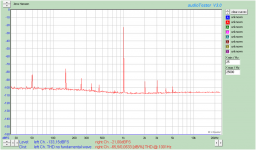
Re grounding issues and artifacts.......
My new PC has a large enough battery to run the PC AND power the QA400.... good thing because the only way i get a clean measurement of a signal source is with the PC floating and running only on its internal battery (4.4A/hr). A lot of junk comes from the external power supply from PC maker. Floating the ac cord ground pin of the charging PS didnt help... only removing it from its charging role by disconnecting it from the PC.
I think my other smaller PC's didnt have enough battery capacity for both or was marginal. ... besides the USB cable and software issues (solved).
-Richard
BTW -- SSD is great -- under 2 seconds to boot up system/everything from cold start.
Last edited:
Re grounding issues and artifacts.......
My new PC has a large enough battery to run the PC AND power the QA400.... good thing because the only way i get a clean measurement of a signal source is with the PC floating and running only on its internal battery (4.4A/hr). A lot of junk comes from the external power supply from PC maker. Floating the ac cord ground pin of the charging PS didnt help... only removing it from its charging role by disconnecting it from the PC.
I think my other smaller PC's didnt have enough battery capacity for both or was marginal. ... besides the USB cable and software issues (solved).
-Richard
BTW -- SSD is great -- under 2 seconds to boot up system/everything from cold start.
I must of missed what SSD is?
Solid State Disk ?
Thanks.
Too many acronyms.
Now the power amp guys want to use GMF (Gain Margin Frequency).
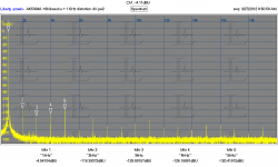
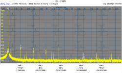
Some may wonder - its been awhile - to recall just what the oscillator section of the unmodified/stock HP-339A does - THD-wise:
This is a stock unit. 10Khz and 1Khz. It's pretty good and better than the stock 339A analyzer section says it is.


Just add another zero (0) to those numbers after mods.
Thx-RNMarsh
This is a stock unit. 10Khz and 1Khz. It's pretty good and better than the stock 339A analyzer section says it is.
Just add another zero (0) to those numbers after mods.
Thx-RNMarsh
Last edited:
Anyone having a hard time repairing a 339A due to a defective reed relay can use a 5vdc reed relay from Radio Shack (USA). Fits the space (I placed it under the pcb and just removed the series R to the reed relay coil and rerouted the R to the new relay coil on the underside of the pcb. [Its a hassel to get the old one out].
The symptoms of a bad relay is that you get no signal voltage reading when the Function switch is in the read Osc Level position.
Thx-RNM
The symptoms of a bad relay is that you get no signal voltage reading when the Function switch is in the read Osc Level position.
Thx-RNM
Higher-Order State-Variable Oscillators
An idea I've been pondering for some time is the use of state-variable oscillator topologies with higher order than the usual second. Such offer improved rejection of distortion from the leveling loop. One of the very few resources on higher-order state-variable filters is this one: linriley.pdf
Here is an adaptation as 4th-order oscillator: 4th-order_state-variable_oscillator_r1.pdf
This is just a proof of concept, without any optimization. Simulated settling time is ~150 ms after startup.
For a tunable oscillator the extra cost of switching the feedback network of more integrators is probably higher than that of a better leveling loop, but for a fixed frequency "reference" design, or "cost no object" DIY, it might be worth considering.
Samuel
Last edited:
Hi Samuel
Have you run a Monte Carlo sim, to see how close matched the C's and R's has to be?
I've looked into something similar and found that close matching was essential.
Stein
- Home
- Design & Build
- Equipment & Tools
- Low-distortion Audio-range Oscillator