Yes, interesting. I suspect the harmonic content there is coming from the mute, rather than the trumpet; that the trumpet is energising a secondary re-radiation from some active element in the mute. Being outside the horn, it's not limited by the normal horn roll-off. I looked up the Harmon mute:
"The Wah-wah mute (also known by the brand name Harmon) is a hollow, bulbous mute in two parts. Unlike the more common straight or cup mutes, the Harmon mute has a solid ring of cork that completely blocks all of the air leaving the bell, and forces all of the instrument's air column into the mute. In a hole on the front of the mute, there is a cup on a tube that can be slid in or out, or removed completely, depending on the composer's direction or the player's preference. The mute produces a sound perhaps best described as a highish-pitched 'buzz'. Harmon mutes are available for many brass instruments, but are only commonly used by trumpets and trombones."
Sounds more like a Kazoo than a mute! Indeed, is it fair use of the English language to call something that brightens the tone a "mute"?!
Even so, the levels around 20kHz are still about 40dB down, so my concerns remain - are we likely to get intermod products of enough energy to be audible, especially in the presence of the complex original sound?
I guess, though, the elegant simplicity of testing at the middle and the extremes as Bob recommends is that you then don't have to worry about these sorts of things! Teetering...
Terry
I got Victor's (vicnic) oscillators today. He has done a marvelous job and I'm quite happy with them and would recommend them to anyone who need a low distortion source.
I'm waiting for the remaining batteries from China to finish the assembly.
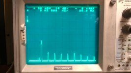
A quick test on the bench with a bench supply got me -130 dB second and -145 dB for the rest at 997 Hz (pretty much the limits of the Shibasoku). The power consumption is very low. I need to clean up the test setup before I can explore further. These are similar to what Victor measured.
The picture below is the distortion spectrum. The first peak is the second harmonic and the rest of the harmonics follow. The top line of the display is -80 dB and the vertical is 10 dB/div.
I'm waiting for the remaining batteries from China to finish the assembly.
A quick test on the bench with a bench supply got me -130 dB second and -145 dB for the rest at 997 Hz (pretty much the limits of the Shibasoku). The power consumption is very low. I need to clean up the test setup before I can explore further. These are similar to what Victor measured.
The picture below is the distortion spectrum. The first peak is the second harmonic and the rest of the harmonics follow. The top line of the display is -80 dB and the vertical is 10 dB/div.
Attachments
Here is the unfinished design for the fast settling state variable oscillator. It borrows the additional peak detecting ideas from Cordell's oscillator, adding more and uses a trick I have used making an LM339 work as a peak detector.
You may have a look here as well
I'll try to get more data on the oscillator. The output is approx 2.7V full up. It has been stable for voltage (+/- .01dB) and frequency (995 Hz) for a day. I have been running it essentially unloaded. The pot and connector aren't even soldered in yet. The bulk of the measured distortion is second at -130dB++. This is good enough to test the limits of any ADC chip made today.
I'll get to the HF modules when I get to the chassis assembly phase in a week or two.
I'll get to the HF modules when I get to the chassis assembly phase in a week or two.
You may have a look here as well
Its quite interesting. We are headed to the same goal. His implementation uses a few more parts to get to the same place.
My 1kHz oscillator from Victor came in today. So far, I've only had time to power it up and check it on Visual Analyser via the Sound Blaster card on my workshop desk computer. Came in at 0.002%, but I'd be confident that that is the soundcard talking. So now I need one of Dick's active twin-tee filters to give the soundcard a sporting chance. Or a much better soundcard. Or both. Sigh....
Anyone planning to lay out the twin-tee filter? I'd hate to do that myself only to find out 237 other people have done it before me. And all of them better than mine.
Terry
Anyone planning to lay out the twin-tee filter? I'd hate to do that myself only to find out 237 other people have done it before me. And all of them better than mine.
Terry
I didn't see much point in measuring harmonic distortion at 10kHz or so, as I was not going to hear even gross 2nd harmonic distortion at 20kHz, let alone 3rd at 30k. I'd be interested in comments on that strategy.
Terry
Yes, but if an amplifier exhibit some amplitude distortion at 10 kHz, it exhibit others distortions, such intermodulation, which are audible when you listen a more complex audio signal... You listen music, no sinewaves
")
Apologies for my bad english !
Yes, but if an amplifier exhibit some amplitude distortion at 10 kHz, it exhibit others distortions, such intermodulation, which are audible when you listen a more complex audio signal... You listen music, no sinewaves
Apologies for my bad english !
If you think your English is bad, what till you hear my French.
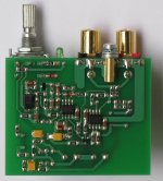
After studying the ebay pcb pix, I thought it appeared similar to a JanasCard inverting Wien bridge but with a jfet AGC. The seller said it was similar but used his own AGC jfet design with 1/2 D-S fed to G for second harmonic reduction.
The seller also indicated he was comtemplating posting the schematic here or on his ebay ad.
A couple of these with a good summer and output circuit could make a nice IM generator.
Looks like I snagged the last one on eBay U.S. So, this is the one to get then? I'm impressed. The SMD's look like they were done by hand. I hope he continues to produce them.
Attachments
I think a twin t notch specific to the oscillator would be great. I would like one that has a balanced input as well which means critical tuning of two filters. But, if the q is optimized and the notch depth is 40 dB then passing the output to a conventional analyzer will make everything easier to manage.
I started on this and got stymied when the spice sim did not work right. I need to figure it out before committing to a PCB (which would be a simple expresspcb design). I have attached the sim if anyone is interested in showing me my mistake. . .
I started on this and got stymied when the spice sim did not work right. I need to figure it out before committing to a PCB (which would be a simple expresspcb design). I have attached the sim if anyone is interested in showing me my mistake. . .
Attachments
I think a twin t notch specific to the oscillator would be great. I would like one that has a balanced input as well which means critical tuning of two filters. But, if the q is optimized and the notch depth is 40 dB then passing the output to a conventional analyzer will make everything easier to manage.
I started on this and got stymied when the spice sim did not work right. I need to figure it out before committing to a PCB (which would be a simple expresspcb design). I have attached the sim if anyone is interested in showing me my mistake. . .
Hi Demian,
It is difficult to tune Twin T's and keep them tuned. I can't imagine trying to keep two tune together. The notch pivots on the head of a pin. Can the balanced part be done a different way that doesn't require two filters? Take a look at what Dick Moore had to do with his to get the tuning stable.
Is the idea of balance for interface to balanced inputs/outputs or is there another reason that I have missed?
David.
I have built a version of Dick's tee filter using seven discrete frequencies rather than continuously tuneable, 20Hz thru 100Khz. It works very well but has not been optimized as yet, may not be better than you might do.Anyone planning to lay out the twin-tee filter? I'd hate to do that myself only to find out 237 other people have done it before me. And all of them better than mine. Terry
An input buffer has been added, holes are provided to use it inverting, non-inverting or not at all. Since mine is constructed to use either batteries or a lab supply switched in, the board has .1 cog smd caps on IC power pins and 10u tant caps on power rails. I also matched all the caps within .1% so I used 10T 200 ohm pots to fine tune.
The zipped Eagle 6 .brd file was homebrewed, the red traces on top are jumper wires not a two sided board.
My calc says if .01u arm caps are used for 997hz, then 15.963K arm resistors are required. I used about 3K arm resistors for all frequencies but 20hz and matched caps accordingly.
Attachments
My 1kHz oscillator from Victor came in today. So far, I've only had time to power it up and check it on Visual Analyser via the Sound Blaster card on my workshop desk computer. Came in at 0.002%, but I'd be confident that that is the soundcard talking. So now I need one of Dick's active twin-tee filters to give the soundcard a sporting chance. Or a much better soundcard. Or both. Sigh....
Anyone planning to lay out the twin-tee filter? I'd hate to do that myself only to find out 237 other people have done it before me. And all of them better than mine.
Terry
Just bought the parts yesterday for a twin-t filter. Have not laid out the pcb yet, but that will go fairly easy and quick. Got the aluminum enclosure picked out, too- for optimum shielding. I had purchased an oscillator from Victor this past Sunday, as soon as it came up for sale. Least I could do after he was kind enough to display his schematic on the www. I was going to wait to build my twin-t until I could first measure the actual output frequency and cater the twin-t to match as closely as possible.
You are certainly welcome to one of my pcb's, but I am no DaVinci when it comes to circuit boards (see post 180). If you could just cover the incremental cost...
Hi Demian,
It is difficult to tune Twin T's and keep them tuned. I can't imagine trying to keep two tune together. The notch pivots on the head of a pin. Can the balanced part be done a different way that doesn't require two filters? Take a look at what Dick Moore had to do with his to get the tuning stable.
Is the idea of balance for interface to balanced inputs/outputs or is there another reason that I have missed?
David.
Thanks for pointing out my problems with the Twin T. Sometime when you are too close you miss the obvious.
First a little background. I had custom frequencies made for testing ADC's. The 997 Hz (which came out 995 Hz for some reason) was selected to make sure that every bit gets exercised. If the frequency is an exact division of the sample rate it can hide some problems.
The balanced input is to avoid ground problems. Electronic differential amp in front limits you to the distortion performance of the input amp and it will not be as good. Having the filter positioned so the amp cannot degrade in front of the filter is essential. I don't know if a twin H could be made to work, but that's the reason for the simulation. In any case there are a number of parts that need to match very well which may be a problem. My goal was to play with the q and depth to try to get approx 40 dB depth for a 3% or 4% band so its less sensitive to drift and then use a conventional distortion analyzer on the output.
With distortion products at -130 dB or more all of this is more than 30 dB better than most audio products can hope to be.
- Home
- Design & Build
- Equipment & Tools
- Low-distortion Audio-range Oscillator