If you look at Jim William's note on Wein Bridge oscillators he uses an LTC buffer to get more drive and an LT1115 ultra low noise opamp. That combo probably is as close to perfect as you will get with today's IC's for an audio frequency oscillator.
I never got it working and I'm not sure why anymore (that was years ago). I'll try to find the PCB's I made (and the expresspcb files for them) to see what happened.
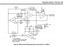
(I suggest reading appendix D of AN43 http://cds.linear.com/docs/en/application-note/an43f.pdf )
I never got it working and I'm not sure why anymore (that was years ago). I'll try to find the PCB's I made (and the expresspcb files for them) to see what happened.
(I suggest reading appendix D of AN43 http://cds.linear.com/docs/en/application-note/an43f.pdf )
Attachments
Last edited:
Lamp Multipler with infinite sample amd hold AGC
HI Guys,
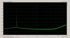
I got the AGC assembled this weekend. It needs a bit of work getting the TC of the integrator right but once it locks it won't let go.
This is 3Vrms @ 2kHz.
I'm having a bit of trouble measuring things.
The elevated noise floor is from the Twin T.
This is an active TT. The 2nd is down -1.78dB and the rest is -0.7dB.
Cheers,
HI Guys,
I got the AGC assembled this weekend. It needs a bit of work getting the TC of the integrator right but once it locks it won't let go.
This is 3Vrms @ 2kHz.
I'm having a bit of trouble measuring things.
The elevated noise floor is from the Twin T.
This is an active TT. The 2nd is down -1.78dB and the rest is -0.7dB.
Cheers,
Attachments
Last edited:
If you look at Jim William's note on Wein Bridge oscillators he uses an LTC buffer to get more drive and an LT1115 ultra low noise opamp. That combo probably is as close to perfect as you will get with today's IC's for an audio frequency oscillator.
I never got it working and I'm not sure why anymore (that was years ago). I'll try to find the PCB's I made (and the expresspcb files for them) to see what happened.
(I suggest reading appendix D of AN43 http://cds.linear.com/docs/en/application-note/an43f.pdf )
I have that buffer ic among others. I'll try them all out again with my SVO.
I might try something discrete or a mixed bag as well.
I found all of one make/brand did not work as well as mixed opamps from various brands/makers. Something the mfr can not do in public. For example, a AD797 and agc controlled by an LT1037 for the KH4402B. That combo produced results well under .0001%.
Other osc brands liked different combo's. It doesn't appear universal as it depends on the RC circuit values which the opamps works with etc.
Thx-RNMarsh
Other osc brands liked different combo's. It doesn't appear universal as it depends on the RC circuit values which the opamps works with etc.
Thx-RNMarsh
HI Guys,
I got the AGC assembled this weekend. It needs a bit of work getting the TC of the integrator right but once it locks it won't let go.
This is 3Vrms @ 2kHz.
I'm having a bit of trouble measuring things.
The elevated noise floor is from the Twin T.
This is an active TT. The 2nd is down -1.78dB and the rest is -0.7dB.
Cheers,
Thats a nice looking plot when the floor is near the 24bit limit of 144dB !! Nice going.
Thx-RNMarsh
In sampling various osc and harmonic analyzers lately, none of them use the most current (Except newest A-P) opamps. Just changing out the old for the new opamps can improve the S/N and harmonic levels 20dB or more. So, if -120 is for an old design, it should be quite do-able to get to -140dB with best practices, parts and opamps. [notice I didnt say - easy - just do-able]
Thx-RNMarsh
No, Demian is closer to the truth. Op-amps floored out on noise (~1nV/rt-Hz) 20yr ago. There is never going to be one 20dB better on noise, the only substantial improvements are had in circuit architecture for linearity at higher and higher BW. Distortion and artifacts are at fixed frequencies, long FFT's and averaging resolve them over the noise.
Same goes for resistors, 1000 Ohm real parts of frequency determining networks will never be < 4nV rt-Hz.
Last edited:
No, Demian is closer to the truth. Op-amps floored out on noise (~1nV/rt-Hz) 20yr ago. There is never going to be one 20dB better on noise, the only substantial improvements are had in circuit architecture for linearity at higher and higher BW. Distortion and artifacts are at fixed frequencies, long FFT's and averaging resolve them over the noise.
Sounds good on paper but has not tested that way on actual instruments being sold from 20 years ago. The HP, KH and others have had their noise drop 20+ dB with opamp changes. If 1nV is the practical limit then the products upgraded where not at anywhere near that 1nV/sqrt-Hz limit yet.
yes, i understand the FFT process got the observed noise floor down.... I rather liked the clean floor without artifacts in it. Now for a really clean, artifact free oscillator at multiple freq that is below the -144dB level.... then we have a nice piece of test equipment.... several way of approaching this is being explored and I support them all.
The best oscillator design i and others pointed out is the -140dB or more thd from www.janascard.cz.
Thx-RNMarsh
Last edited:

I remember that being explored some time ago. There were several issues. First the resistors around the LDR were not necessarily connected right. Second there was some question about the -140 dB thd. I would question it with the LDR in the link since the LDR has a very significant voltage coefficient (at -140 and detectable nonlinearity becomes significant). I believe someone built it but that was months ago.
At 3V out the feedback current is around 3 mA. If the LDR contributes 3 nA of nonlinear current that would be -120 dB. to get to -140 dB it needs to be around 30 pA. 30 pA is not very much. The input current noise of the LME49710 is listed as 1.6 pA/rtHz. The voltage noise is listed as 2.5 nV/rtHz. I think the noise floor will limit the THD+N to something around -136 dB at best at 3V out.
At 3V out the feedback current is around 3 mA. If the LDR contributes 3 nA of nonlinear current that would be -120 dB. to get to -140 dB it needs to be around 30 pA. 30 pA is not very much. The input current noise of the LME49710 is listed as 1.6 pA/rtHz. The voltage noise is listed as 2.5 nV/rtHz. I think the noise floor will limit the THD+N to something around -136 dB at best at 3V out.
I have that buffer ic among others. I'll try them all out again with my SVO.
I might try something discrete or a mixed bag as well.
The light bulb agc seems to be really good. I noticed in AN43 a reference to using 4 bulbs in series for low frequencies and part numbers.
You must wrap the buffer in the feedback for the opamp. Its pretty free of high order nasties but only in the .1% distortion range without the feedback. It has a lot of drive and allows the opamp to run at full open loop gain.
Hi Demian,
I've used the buffers wrapped around op amps before.
I'm familiar with the app note. The lamps work a bit different in the multiplier. Not nearly as much signal is seen in the lamps as with a Wien bridge. It's mostly dc from the lamp drivers. The signal in the lamps is riding on the control voltage and the lamps behave a bit different under these conditions. The lamp effect normally seen in the classic Wien Bridge is not present in this design. Which is fortunate.
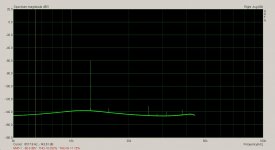
I found a single TC for the integrator which works in all ranges. The OSC settles in exactly the same time for each range from power up which is under 5 seconds. I can improve on this more by putting an offset on the lamps drivers to a mid point of the multiplier gain.
I've found the lamps have a LP effect on the drive voltage which adds a Lp filter to the Vc of the AGC. The differential drive also rejects noise and ripple on the Vc. All these things add up to even better performance.
I'm pleased with the results all around.
This is around 12kHz @ 3Vrms.
I need a quite power supply for this. Currents approaching 300mA not including a buffer/driver.
Cheers,
Attachments
Last edited:
@RNMarsh
A PCB design actually does exist. I made one a couple of weeks ago. It also includes the Twin-T filter. But: I am waiting for the PCB to arrive from the PCB vendor, so performance is still TBD.
I plan to start with the LME49710 op-amp, but I may also try out other op-amps, to check the performance. In terms of noise the OPA209 looks interesting with the impedances used in the circuit, but I am not sure the distortion performance will be equally good.
The AD797 may be too noisy (current noise).
The OPA1611 could perhaps also be worth trying.
The PCB layout was made for SMD op-amps (but leaded resistors and capacitors in the oscillator section), so it is not the easiest to use for swapping op-amps.
@RNMarsh
A PCB design actually does exist. I made one a couple of weeks ago. It also includes the Twin-T filter. But: I am waiting for the PCB to arrive from the PCB vendor, so performance is still TBD.
I plan to start with the LME49710 op-amp, but I may also try out other op-amps, to check the performance. In terms of noise the OPA209 looks interesting with the impedances used in the circuit, but I am not sure the distortion performance will be equally good.
The AD797 may be too noisy (current noise).
The OPA1611 could perhaps also be worth trying.
The PCB layout was made for SMD op-amps (but leaded resistors and capacitors in the oscillator section), so it is not the easiest to use for swapping op-amps.
That is good to know... I hope it works well. How will you measure the THD with the LME or compare performance of various opamps? What is the test and measurment system that you use?
Thx-RNMarsh
Last edited:
I plan to use the filter and either
1: A R&S UPL Audio Analyzer.
2: My own ADC design based on a Cirrus Logic CS5381 + audioTester on the PC.
I have used solution no. 2 for a number of tests at work with good results. A limitation is that the maximum input signal is 2Vrms balanced. But hopefully the distortion after the filter and 60 dB of gain will not be that high") Then I have other problems!
Then I have other problems!
1: A R&S UPL Audio Analyzer.
2: My own ADC design based on a Cirrus Logic CS5381 + audioTester on the PC.
I have used solution no. 2 for a number of tests at work with good results. A limitation is that the maximum input signal is 2Vrms balanced. But hopefully the distortion after the filter and 60 dB of gain will not be that high
Then I have other problems!This and several others are simple and offer no artifacts (harmonics) above -140dB... making DUT measuremenst easy and convenient and for fool-proof test data results:
Let's try it out ---maybe a pcb layout already exists.
Thx-RNMarsh
This circuit has a 4K source impedance at the output with a gain of three or so for about 24nV/rt-Hz noise at best, no op-amp choice can improve that. That was the issue I was addressing. To make this circuit have 20dB worse noise would be hard.
The LME part has 1.6pA/rt-Hz current noise so its low voltage noise is already not relevant.
Last edited:
So lets lower the source R to the practical smallest amount, then.
Why is this so hard to do? Just make an osc with best performance -- with best opamp and get as low noise and thd as possible.
can the circuit be scaled so the values give best noise and thd performance with the most appropriate opamp?
Scott... you've made us a great opamp. can you help us make a great osc with both lowest noise and thd possible?
Thx-RNMarsh
Last edited:
I plan to use the filter and either
1: A R&S UPL Audio Analyzer.
2: My own ADC design based on a Cirrus Logic CS5381 + audioTester on the PC.
I have used solution no. 2 for a number of tests at work with good results. A limitation is that the maximum input signal is 2Vrms balanced. But hopefully the distortion after the filter and 60 dB of gain will not be that high
can we make a copy of your ADC design to use? Do you have any data on its performance?
Thx-RNMarsh
Hi Demian,
I've used the buffers wrapped around op amps before.
I'm familiar with the app note. The lamps work a bit different in the multiplier. Not nearly as much signal is seen in the lamps as with a Wien bridge. It's mostly dc from the lamp drivers. The signal in the lamps is riding on the control voltage and the lamps behave a bit different under these conditions. The lamp effect normally seen in the classic Wien Bridge is not present in this design. Which is fortunate.
I found a single TC for the integrator which works in all ranges. The OSC settles in exactly the same time for each range from power up which is under 5 seconds. I can improve on this more by putting an offset on the lamps drivers to a mid point of the multiplier gain.
I've found the lamps have a LP effect on the drive voltage which adds a Lp filter to the Vc of the AGC. The differential drive also rejects noise and ripple on the Vc. All these things add up to even better performance.
I'm pleased with the results all around.
This is around 12kHz @ 3Vrms.
I need a quite power supply for this. Currents approaching 300mA not including a buffer/driver.
Cheers,
Are you going to make a pcb layout for it to be built (DIY) or make some pcb's for us to buy?
- Home
- Design & Build
- Equipment & Tools
- Low-distortion Audio-range Oscillator