Dick, I think Samuel is talking about the noise. At 100K BW and -130dB below 1V rms that's 1nV/rt-Hz. That means that if the resistive components of your frequency determining network are <50 Ohms there is still no known op-amp for your oscillator. Then of course there is no room for the distortion. There is no substitute for long averaged FFT's, this brute force approach is really just academic.
Its a good point --- I dont pretend to know how the thd +n is done in the analyzer. Maybe it isnt thd+n but just displaying thd? the meter needle jumps around so it looks like noise and when i drop the noise but not the thd, the meter reading drops etc etc. It does an FFT internally and can display the total or individual harmonics of 2H, 3H, 4H and 5th Harm... but on a meter type readout.
On the better osc I just see 2H and 3H levels. The 4402B spec in midrange is below -120dB by factory spec as shown. It measures that way also here and can be tuned to drop lower. So??? And, the spec from Victor's osc measures right in there were he says it is. Is this thing an FFT? I dont know... cant find schematics/manual. maybe it is. Everything seems to correlate well with claims and measurements here and from others--- in some cases it measures at the limits of the analyzer. Note the display of the harmonics (a meter reading rather than the usual scope type display) is .0003% full scale or -110dB and -20dB on that scale is easy to read -- -130dB. below that is a guess but still readable by another 10dB. I guess that means it must be an FFT/DSP product in disguise?
Thx-RNMarsh
Last edited:
True. But the biggest issue for me is the lack of a few key frequencies, such as 50 or 100hz to do a LF fft up to at least the 50th harmonic, and 19k and 20k for CCIF IMD test (plus some synchronization!)
You missed some of the work on the HP 339A perhaps.... this is the same reason I was interested in modifying it with davada's help... multiple frequencies.... I have carried this forward to other osc with selectable/multiple freqs. Eventually, I will sell off all of them and keep one or two (for IM). Others may want to do same mods and I can tell them how, exactly, for the models I have looked at - so they dont need to buy the best analyzer nor try various osc models. i'm giving myself a quick lesson in what the practical limits are and when done I will be able to do testing of amps quickly and at any freq quickly and accurately.
At the same time I am following the low cost FFT route. However, if the software isnt universally workable and easy to get running on any pc then I will just buy a dual channel HP or SRS or TEK FFT and be done with it.... import the files into analyzes software and do all sorts of things besides harmonic extractions.
Thx-RNMarsh
Here is the thd(+n ?) off the meter and the harmonics off the monitor output via HP 3580:
Off the meeter it is reading near -127-8dB. Off the monitor port, the 2H is near the -140 line (-138) and the 3H is near the noise floor of -155dB re 1 volt at -148dB.
This is for the average tuning for wide range of freqs. I can tune below -130db thd (+N ?) on the meter display at just 1 freqs -- like 1Khz.
Thx-RNMarsh
Last edited:
Its a good point --- I dont pretend to know how the thd +n is done in the analyzer. Maybe it isnt thd+n but just displaying thd? the meter needle jumps around so it looks like noise and when i drop the noise but not the thd, the meter reading drops etc etc. It does an FFT internally and can display the total or individual harmonics of 2H, 3H, 4H and 5th Harm... but on a meter type readout.
On the better osc I just see 2H and 3H levels. The 4402B spec in midrange is below -120dB by factory spec as shown. It measures that way also here and can be tuned to drop lower. So??? And, the spec from Victor's osc measures right in there were he says it is. Is this thing an FFT? I dont know... cant find schematics/manual. maybe it is. Everything seems to correlate well with claims and measurements here and from others--- in some cases it measures at the limits of the analyzer. Note the display of the harmonics (a meter reading rather than the usual scope type display) is .0003% full scale or -110dB and -20dB on that scale is easy to read -- -130dB. below that is a guess but still readable by another 10dB. I guess that means it must be an FFT/DSP product in disguise?
Thx-RNMarsh
There is often confusion between noise and signal specific reading. The 725 highlights this. The THD+N reading has both and indicated the total energy in the band, including noise harmonics and non-harmonic stuff (like hum). The noise floor is limited by the input amp. If its -130 dBV in 100 KHz that's the equivalent to the noise of a 50 Ohm resistor at room temperature. Its also close to the best you can get, possibly better than you can get with a amplifier if the band stretches down to below 20 Hz (1/F noise will dominate). I did a quick check on my 725 and posted what I saw earlier. It was close to 5 nV/RtHz, considerably higher than 1 nV/RtHz. Actually the light bulbs in series with the input (protection) may be more than 50 Ohms cold. I hope to know soon.
The distortion measurement effectively creates narrow band filters. the noise in a band is proportional to the band width. If the filters are in effect 100 Hz then the same 50 Ohm resistor would have a noise floor of -160 dB in that band. Any distortion would not show below -160. The process it uses to capture the distortion still eludes me (The patent did not explain in simple terms) but it does only look at harmonics. I tried adding a "marker" as per Victor's latest efforts and if the marker was not perfectly on frequency I got strong beat notes (even if its 40 dB stronger than the internal harmonic). Fortunately the Boonton can be tuned in .01 Hz steps.
The other way to increase the SNR of the source is to make it bigger. The AG16 can deliver 10V which is significantly higher and makes for a better SNR. However its limited by the 600 Ohm output.
I use the direct output port from the oscillator .... 7v rms.
The noise of analyzer only appears as -160dB
As you can see from the pictures, the osc was at almost -130dB thd + or - the noise. And, i can tune it lower... matching Victor's single freq osc. (as I measured). It is what it is.
-Thx-RNMarsh
The noise of analyzer only appears as -160dB
As you can see from the pictures, the osc was at almost -130dB thd + or - the noise. And, i can tune it lower... matching Victor's single freq osc. (as I measured). It is what it is.
-Thx-RNMarsh
Last edited:
Here is the THD (+N ?) off the meter and the harmonics off the monitor output via HP 3580:
This is likely a THD measurement. You'd probably need to de-activate the "Analysis" button in the "MEAS FUNCTION" section for THD+N. And you should switch to RMS in the "RESPONSE" section.
Samuel
This is likely a THD measurement. You'd probably need to de-activate the "Analysis" button in the "MEAS FUNCTION" section for THD+N. And you should switch to RMS in the "RESPONSE" section.
Samuel
On a more careful look, this is correct. The harmonic level shown is in fact THD. [in this case, only 1 dB difference between average and rms]
I tune the oscillator in the analyzer mode to see 2H and 3H and adjust for lowest THD usually.
Thx-RNMarsh
Last edited:
The noise level is monitored on the HP3580.... I can see the shape of the noise not just total added.
progress is being made... lower noise and THD. But I wont get to -140 THD+N this way. But it is pretty good and better than stock for relatively low cost used gear of yester-year.
BTW--- The Panasonic VP-7723, which is coming, is more like the HP339A as it has osc and analyzer in same chassis and is spec'ed for very low distortion (THD). But it appears to be built in a more substantial way as well as better specs.
Thx-RNMarsh
Last edited:
because I am not really interested in measuring the noise floor of an amplifier at this time; Just the harmonics of an oscillator that I wish to reduce the THD/harmonics. It happens that the better parts and opamps are also lower noise than the original ones. And, that helps continue the pursuit of lowering the harmonics of the oscillator.
Next up -- another oscillator: The VP-7723A just arrived and its oscillator looks promising at THD of .0001% (1v/1KHz) on the ShibaSoku 725. The VP7723a also includes an analyzer so I can compare against the SibaSoku 725. This VP-7723a was from Hitech&lab in Japan. Thru the monitor of the ShibaSoku 725 again 2H is -133 and 3H is -150. Noted the noise floor is at -160 now... so the 7723a gen is a little quieter than the KH4402B.

Thx-RNMarsh
Next up -- another oscillator: The VP-7723A just arrived and its oscillator looks promising at THD of .0001% (1v/1KHz) on the ShibaSoku 725. The VP7723a also includes an analyzer so I can compare against the SibaSoku 725. This VP-7723a was from Hitech&lab in Japan. Thru the monitor of the ShibaSoku 725 again 2H is -133 and 3H is -150. Noted the noise floor is at -160 now... so the 7723a gen is a little quieter than the KH4402B.
Thx-RNMarsh
Last edited:
The question comes up... couldnt you just use an FFT to do the harmonic measuring and a seperate sensitive ac voltmeter to measure noise and accomplish the same thing?
Yes.
IF they dont have artifacts, dont have software issues, dont cost the earth to own and dont have enough bits, etc etc etc. There is a lot of potential for low cost FFT but they arent ready for Prime Time, yet.
So I am making good with what I have and what is easily and readily available as used test equipment. Another versatile instrument I am looking for would be a good high speed transient capture instrument with sufficient resolution -- then import the data into software.
-RNM
Last edited:
I do wish these FFT software packages would allow us to plugin our own windowing, filters etc. Or at least allow the data to be dumped to a file for further analysis. I looked over that paper that Samuel linked to a while back. There is some pretty impressive work done there.
The bottom line is you can always measure the noise floor of an amplifier in the absence of any signal. Why try to do it at the same time?
Personally I don't use a THD+N function primarily to measure distortion and noise at the same time. But I find viewing the time domain residual on a scope to be tremenduously helpful for diagnosing unexpected distortion issues--the temporal alignement, or the possibility to see distortion changes in real time (which rules out using the average function of the scope to average noise in the time domain), gives numerous clues. These considerations apply particularly for converter testing, where various noise-like artefacts (from improper dithering, gain ranging etc.) may only show up with signal stimulus. So there is certainly some benefit from also improving the THD+N of a generator.
Another versatile instrument I am looking for would be a good high speed transient capture instrument with sufficient resolution -- then import the data into software.
I'm not quite sure why it needs to be "high speed" (which implies for me MHz or even GHz) for what we're doing. A decent pro audio interface (e.g. RME, Motu, Benchmark) should cover most needs.
I could design a very good DYI ADC box (and I might do it once), but there's just so much time left.
Samuel
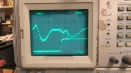
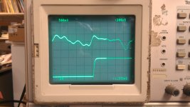
This is a picture of the waveform at the distortion analysis output of the 725 for the 590AR and my KH2200 function generator. There is around 70 dB difference in level between the two pictures. The lower trace is the sync output.
If you understand what you are looking at you can infer where the distortion is coming from (crossover, too much/too little gain at a certain part of the wave etc.). Tweaking the diode array in the KH2200 would be really easy with this.
If you understand what you are looking at you can infer where the distortion is coming from (crossover, too much/too little gain at a certain part of the wave etc.). Tweaking the diode array in the KH2200 would be really easy with this.
Attachments
This is a picture of the waveform at the distortion analysis output of the 725 for the 590AR and my KH2200 function generator. There is around 70 dB difference in level between the two pictures. The lower trace is the sync output.
If you understand what you are looking at you can infer where the distortion is coming from (crossover, too much/too little gain at a certain part of the wave etc.). Tweaking the diode array in the KH2200 would be really easy with this.
Those old TEK scope just keep on going.
Is this an impulse test?
The Teks are a real value. I have spares since they are so cheap around here, compared to the hassle of repair.
This is similar to the monitor output with the noise removed. The digital part does a synchronous sampling and seems to only see harmonics. The lower trace is a sync for the scope
This is similar to the monitor output with the noise removed. The digital part does a synchronous sampling and seems to only see harmonics. The lower trace is a sync for the scope
The Teks are a real value. I have spares since they are so cheap around here, compared to the hassle of repair.
This is similar to the monitor output with the noise removed. The digital part does a synchronous sampling and seems to only see harmonics. The lower trace is a sync for the scope
From the patent it's hard to tell. I thought the harmonics were separated using BP filters after reconstruction, The digital deals with the noise and reconstruction is at a single frequency. Different interpretations of the patent.
These considerations apply particularly for converter testing, where various noise-like artefacts (from improper dithering, gain ranging etc.) may only show up with signal stimulus. So there is certainly some benefit from also improving the THD+N of a generator.
I could design a very good DYI ADC box (and I might do it once), but there's just so much time left.
Samuel
Pls do design one... PLS !! We need one. You'll get plenty of help. Many of us are in the final quarter of the game before the buzzer. Getting down our experience is something important... Now we have the world watching and listening via the WWW/Internet. A once in a life-time opportunity.
")
Thx-RNMarsh
- Home
- Design & Build
- Equipment & Tools
- Low-distortion Audio-range Oscillator