Hello!
I recently replaced the rotary switch on my Fluke 87 (1st gen) multimeter and all is well except for one thing. The "AC" and "DC" that displays on the LCD is stuck on one or the other.
For instance: When I switch the dial from the off position to AC volts "AC" is displayed on the LCD. When I switch the dial from AC volts to DC volts "AC" is still displayed on the LCD. When I switch the dial from DC volts to DC millivolts the LCD switches from "AC" to "DC". When I turn the dial from DC millivolts to DC volts "DC" is displayed on the LCD. But when I switch from DC volts to AC volts "DC" is still displayed on the LCD.
This does not look right to me. I don't use this meter on a daily basis so I cant remember if it did this before I replaced the rotary switch????? Just does not look right to me.
A few side notes:
Thanks in advance!
I recently replaced the rotary switch on my Fluke 87 (1st gen) multimeter and all is well except for one thing. The "AC" and "DC" that displays on the LCD is stuck on one or the other.
For instance: When I switch the dial from the off position to AC volts "AC" is displayed on the LCD. When I switch the dial from AC volts to DC volts "AC" is still displayed on the LCD. When I switch the dial from DC volts to DC millivolts the LCD switches from "AC" to "DC". When I turn the dial from DC millivolts to DC volts "DC" is displayed on the LCD. But when I switch from DC volts to AC volts "DC" is still displayed on the LCD.
This does not look right to me. I don't use this meter on a daily basis so I cant remember if it did this before I replaced the rotary switch????? Just does not look right to me.
A few side notes:
- This meter is 17+ years old and is the first gen 87 model.
- I replaced the switch due to the batteries dying within a few weeks of being replaced with new ones. I assumed the rotary switch was causing a parasitic drain on the battery because it was pretty worn and when I would put a new battery in the display and back-light would flicker while the rotary dial was in the off position.
- The new switch is a brand new genuine Fluke part.
- My soldering joints look perfect and I cleaned all of the old flux off of the board afterwards.
- I also cleaned the LCD contact points on the PCB as well.
- I performed the "Rotary Switch Test" per Flukes service manual and the meter displays the correct values.
Thanks in advance!
It sounds as if you maybe have another problem such as leakage on the board. I'd carefully examine the board for any corrosion areas. If you still have it I'd also carefully compare the old switch with the new one. What did you clean up your flux with? Could it have left a conductive residue? My favorite cleaners since freon went away are either acetone or Anhydrol. Anhydrol is a mix of ethyl and methyl alcohol with no water. A major problem with LCD circuits is it takes so little current to change things.
Hope this helps.
Doc
Hope this helps.
Doc
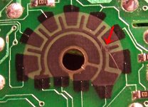
I figured out what is wrong....there were some hardened chunks of rosin on some of the solder joints when I finished. I took a scraping tool to clean them off and I slipped and scored the surface of the black conductive material on the back of the board that the wiper makes contact with. I thought I only scored it but nope, I completely severed the circuit.
I hit the severed area with a black sharpie hoping that would work but it didn't.....DERP!
Do you guys think one of those conductive circuit pens would work to repair the trace? I am willing to spend the $20 or so if it will work but I am unfamiliar with what this black conductive material is and dont want to waste the money if it will not work.
Thanks for the replies.
Attachments
Ouch. That may be hard to fix. I don't know much, but I know the Sharpie won't do any good. 
The black stuff isn't perfectly conductive, it has some resistance. Maybe a heavy coat of pencil lead (graphite)? Probably wouldn't last long, even it happened to work. The conductive pen sounds like it might work though.
The black stuff isn't perfectly conductive, it has some resistance. Maybe a heavy coat of pencil lead (graphite)? Probably wouldn't last long, even it happened to work. The conductive pen sounds like it might work though.
Rather than a conductive circuit pen I'd go for some conductive paint or epoxy. GC used to make conductive paint in a small bottle for painting sheilds and such. MCM electronics might carry it. The stuff you scratched is likely either a metal film or carbon mix. New pencils won't work as they aren't graphite anymore. Use another OHM meter on a section of the trace to get an idea of just how conductive it needs to be. That will give you an idea of what you can get away with using. You might try measuring a section of Carpenters pencil (wide and flat) to see how conductive the lead is. Then experiment grindng some of it and mixing in epoxy. (Do tests on a piece of paper, not your meter.)
Doc
Found some: Silver Paint, 18% Silver, 15 gram brush-cap bottle
Here's a make some link: Make Conductive Glue, Conductive Paint, and Conductive Ink
I found at least two other sites, one insanely expensive and another 1/2 pint minimum size (but reasonable).
Doc
Found some: Silver Paint, 18% Silver, 15 gram brush-cap bottle
Here's a make some link: Make Conductive Glue, Conductive Paint, and Conductive Ink
I found at least two other sites, one insanely expensive and another 1/2 pint minimum size (but reasonable).
Last edited:
- Status
- This old topic is closed. If you want to reopen this topic, contact a moderator using the "Report Post" button.
- Home
- Design & Build
- Equipment & Tools
- Fluke 87 problem after rotary switch replacement.