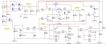
In the past few weeks I have built the power supply below. I have tested it to 25V and 5.5A. With an appopriate transformer it can do up to 35V.
There are two channels one positive and one negative. Voltage regulation is done with the LM317BT and LM337BT. To achieve currents in excess of 1.5A I used a bypass transistor (MJL3281A and MJL1302A).
Current limiting is performed with a .25R sense resistor and an op-amp (MC33072).
R1 slowly discharges the 10mF capacitor.
R6 presents a load on the LM317/337 otherwise the output may rise. This can be improved with a constant current source so that the current remains constant througout the range but I had already run out of board space.
R8 and R9 limit the very high voltages (both can be omitted if we are confident of no mistakes during assembly).
R14 sets a minimum level for current limiting to avoid a "dead-zone" on R13 due to the first diff op-amp having a minimum working level (eg 100-700mV). On the negative channel, there are some differences. There the op-amp "idles" close to 0V which, as far as the op-amp is concerned, is equivalent to max supply rail. The best we can get there is 500mV-1500mV off the top rail, so I used D17 to raise the idle voltage past this level. Actually in my circuit I had to add 4 * 1N4148 in series. Ideally R14 should be a trim-pot around 10K.
C16 is needed to avoid high frequency oscillations due to R26. I used 68nF randomly (it seemed to stop the oscillations), other values will also work.
The transistors are MJL3281A and MJL1302A. I mounted them on a large-ish heatsink, have not tried in anger yet to see how hot it will get. Adding a fan would be a great idea if we plan to pull lots of amps on a regular basis.
The rectifier diodes 1N5402 are only 3A - a 6A version is needed (I am running mine on the 3A ones but do not draw 5A regularly. I will replace with 6A diodes as soon as possible).
I have also added a 6.3A fuse just before the rectifier diodes and there is a 3A-5A fuse on the mains socket to protect the transformer (in my case 2x25V, 300VA).
I also added LED panel meters for voltage and current measurement. These most likely need to be powered from independent power sources, independent of the two main channels but also independent between the panel meters. In my first attempt I did not realise that a common power supply for the panel meters results in shorting the two channels so that they cannot be used in series to provide +/- voltage output with a single common. To provide power for the LED panel meters (they need 5VDC at 120mA) I wound 15 turns of 4 wires around the toroidal to get 5VAC (times 4) and built a simple rectifier for each.
Attachments
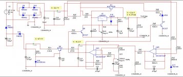
C11 is not 470pF, probably tens of nanos, I have to open the box and look it up. The reason is long wires running to the pots on the front which may introduce instabilities. The diagram also shows the COMMONs earthed - this is just to get the simulation running, there is no earth connection whatsoever.
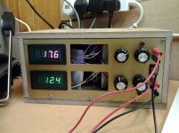
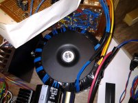
Some pictures of the finished product.
There is a simple wooden box made of plywood. The heavy transformer (300VA) and boards are mounted on another piece of plywood and the whole tray slides in and out of
the box. The front and back panels are etched fibreglass PCBs, the front is sprayed painted with Christmas gold decoration paint.
Only the voltmeters show, the am meters have not arrived yet.
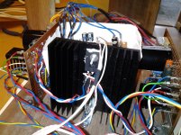
A detail on the transformer I wound 4 extra secondaries to obtain 5VDC to power the 4 panel meters with independent power supplies.
There is a simple wooden box made of plywood. The heavy transformer (300VA) and boards are mounted on another piece of plywood and the whole tray slides in and out of
the box. The front and back panels are etched fibreglass PCBs, the front is sprayed painted with Christmas gold decoration paint.
Only the voltmeters show, the am meters have not arrived yet.
A detail on the transformer I wound 4 extra secondaries to obtain 5VDC to power the 4 panel meters with independent power supplies.
Attachments

Yes, but it is not just the output caps that are problematic. Behind the regulator sits a 10,000uF capacitor. A short at the output is catastrophic.
One of the output transistors blew yesterday and I had to replace it. This is a 200W device capable of withstanding 16A. I do not know how it died, but I suspect I shorted the output accidentally (I was just switching the PSU on - the transistor did not die of increasing heat over time). The 6.3A fast fuse on the transformer's secondary blew too. But it did not protect the output transistor.
So we need something to protect from shorts at the output, both the PSU and the equipment that might be causing the short. A 6A fuse might be helpful here?
In addition I need something to disconnect the output (open circuit) when I switch the PSU off - currently it takes a long time until the voltage drops. I am thinking of a relay. The same relay might also be employeed instead of a fuse to protect from shorts.
Is that a good idea ?
Your current limit circuit can't be working good enough. It pulls down the LM317 o/p to effectively a shorted 1.25v in the event of a s/c o/p and it doesn't do much to limit Q2 current which looks like it's turned hard on by the LM317 conducting from Vin to Vout. Perhaps you need a transistor bypass circuit more like the one shown on page 8 of National Semi's LM317 datasheet as that version monitors the transistor current. The LM317 doesn't need protecting, it has its own internal s/c protection. A relay or fuse for longer term protection is a good idea.
Yes. I am certain the 10mF capacitor provided enough current to blow a 16A transistor. I did not even see a spark, no idea how it happened. As a temporary fix, I have added a 6.3A fuse at the output, less than half of the 16A of the transistors. However if I blow it, then I will have to open the box to replace (a palavar). So I will design a relay circuit that will cut off over a certain current. Maybe also cutoff when you flick the power (as an added bonus).
A fuse is a poor solution, it is too slow, and bipolars do not have I²t ratings.Yes, but it is not just the output caps that are problematic. Behind the regulator sits a 10,000uF capacitor. A short at the output is catastrophic.
One of the output transistors blew yesterday and I had to replace it. This is a 200W device capable of withstanding 16A. I do not know how it died, but I suspect I shorted the output accidentally (I was just switching the PSU on - the transistor did not die of increasing heat over time). The 6.3A fast fuse on the transformer's secondary blew too. But it did not protect the output transistor.
So we need something to protect from shorts at the output, both the PSU and the equipment that might be causing the short. A 6A fuse might be helpful here?
The root of the problem is the immense current regulation loop: you have 3 IC's, of which two are integrators, plus two transistors.
The time between the appearance of a stimulus at one end and the turn off of the transistor at the other is sufficient for the transistor to die 10 times.
In addition, the turn-off is not complete because of the 317.
The only good solution is to redesign the whole thing from scratch, but if you just want to avoid blowing your transistors at the drop of a hat, you could add a fast and crude limitation directly at the transistor level.
You can use the 0.25 ohm sense and connect a PNP to short the base when its Vbe is exceeded (you can use a resistive divider to adjust the current.
The transistor has to be hefty, as it will have to withstand the 317 short-circuit current.
Or you could simply use a number of diodes, as suggested by sbrads.
What I wrote above is merely a technical analysis.Very good idea. Will do it next time I blow a fuse")
I understand it doesn't make pleasant reading, and I have been there too (we've all been there): I have a cemetery of failed projects, each time I didn't think far and deep enough of all the issues involved.
Designing a good lab supply is pretty difficult, especially the current regulation part, and the way it handles the change from V-mode to I-mode.
Opamps tend to remain stuck in saturation and take a long time to awake in case there is an incident.
Here are the two work around options:
Attachments
What I wrote above is merely a technical analysis.
I understand it doesn't make pleasant reading, and I have been there too (we've all been there): I have a cemetery of failed projects, each time I didn't think far and deep enough of all the issues involved.
Designing a good lab supply is pretty difficult, especially the current regulation part, and the way it handles the change from V-mode to I-mode.
Opamps tend to remain stuck in saturation and take a long time to awake in case there is an incident.
Here are the two work around options:
Shouldn't Q2 be a PNP, and D1 - D3 reversed?
Shouldn't Q2 be a PNP, and D1 - D3 reversed?


You are completely right of course: I happily messed up the positive and negative together.
A fuse is a poor solution, it is too slow,
and bipolars do not have I²t ratings.
The root of the problem is the immense current regulation loop:
you have 3 IC's, of which two are integrators, plus two
transistors.
The time between the appearance of a stimulus at one end and the
turn off of the transistor at the other is sufficient for the
transistor to die 10 times.
In addition, the turn-off is not complete because of the 317.
The current limiting ICs and transistor was meant as an addon to
provide some current limiting - which so far it does quite well.
Unfortunately I never thought about shorts too much - and later
realised that shorts are quite common with a bench PSU and wires laid all over the place.
That's a bit harsh - considering that it is all done on veroboardThe only good solution is to redesign the whole thing from scratch
and quite tedious to assemble. Plus, it works
Yes I will do something like that once I have reason to open it up again., but if you just want to avoid blowing your transistors at the
drop of a hat, you could add a fast and crude limitation directly
at the transistor level.
You can use the 0.25 ohm sense and connect a PNP to short the base
when its Vbe is exceeded (you can use a resistive divider to
adjust the current.
The transistor has to be hefty, as it will have to withstand the
317 short-circuit current.
Or you could simply use a number of diodes, as suggested by
sbrads.
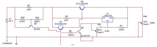
I have done a bit of simulation and the following seems to work well : it is sharp enough as not to interfere with the functioning of the pass transistor or the existing current limiting, until very close to the limit. In the original design most of the current is provided by the external pass transistor and the 317 stays so cool it does not even need a heatsink (but I have put one nevertheless). The design below maintains that balance until there is a short. Not sure how it will behave in practice, will there be sparks when I short it? Will it protect the output transistors? My old, professional bench PSU, a huge device built in the 70s-80s, it would spark if you shorted it.
Attachments
Last edited:
It will work. Of course, the 317 will dissipate a large amount of power during limitation, but it is protected, and you will not deliberately leave a short on the output for extended periods of time.
Now there might be sparks, but that's rather secondary, the important thing is to avoid damages.
Now there might be sparks, but that's rather secondary, the important thing is to avoid damages.
- Status
- This old topic is closed. If you want to reopen this topic, contact a moderator using the "Report Post" button.
- Home
- Design & Build
- Equipment & Tools
- home made desktop power supply