I asked a friend if he could get me a big variac for a nice price. He knew what I needed it for, so I assumed he would find a ~1000VA one.
Since I got it for free, I couldn´t turn it down. Even tho I wish I had when I went to pick it up. Its really really heavy.
The problem is that its 3phase, and I have no idea on how to convert or use it on single phase here at home.
If I just connect ground and two of the three hot wires, will it work?
I know im only getting 2x0-220 instead of 3x0-220, it dont matter.
The goal is to get X-0-X output, e.g 26-0-26 so I can test a chipamp.
Attachments
Just insulate the inputs to the two phases you don't need.
Connect to the remaining Phase and Neutral, just as you would do for single phase Live and Neutral.
Ground, or Earth, or PE are quite separate. None of these are Neutral.
But, ask an electrician to check what voltage it is designed for use with. It could be 220Vac or 400Vac for each phase.
I think you could wire up one or both of the spare phases to give a second and/or third "in-phase" output/s. Again the electrician should be able to confirm.
Live and neutral. Got it.
Come to think of it, I have to connect at least one more fase for X-0-X output.
The correct ting would be....? tie the two live wires together? Tying the live and N together sounds very wrong
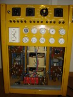
There are 3 large transformers (20cm/8" diameter) and one a tad smaller for the DC outputs.
The large ones have to be for isolation, right? What else reason is there for putting an extra 45kg of Cu inside?
Besides.. voltages below 50v dont scare me very much. To much resistance in our body, so I´ll take my chances with the chip amp.
The Perreaux on the other hand... 80-0-80v makes for a nasty rail voltage.
Come to think of it, I have to connect at least one more fase for X-0-X output.
The correct ting would be....? tie the two live wires together? Tying the live and N together sounds very wrong
There are 3 large transformers (20cm/8" diameter) and one a tad smaller for the DC outputs.
The large ones have to be for isolation, right? What else reason is there for putting an extra 45kg of Cu inside?
Besides.. voltages below 50v dont scare me very much. To much resistance in our body, so I´ll take my chances with the chip amp.
The Perreaux on the other hand... 80-0-80v makes for a nasty rail voltage.
What you've got there actually contains THREE variacs. (I'm well familiar with the configuration, though not that particular piece of equipment).
Take it apart and you will find three cores. May take some dissasembly as they are linked together in a carrier and threaded through with a motorized rotor unit.
After taking apart any one core may be connected to your mains as a normal single phase unit.
I envy you, thats a nice stack!
Doc
Take it apart and you will find three cores. May take some dissasembly as they are linked together in a carrier and threaded through with a motorized rotor unit.
After taking apart any one core may be connected to your mains as a normal single phase unit.
I envy you, thats a nice stack!
Doc
What you've got there actually contains THREE variacs. (I'm well familiar with the configuration, though not that particular piece of equipment).
Take it apart and you will find three cores. May take some dissasembly as they are linked together in a carrier and threaded through with a motorized rotor unit.
After taking apart any one core may be connected to your mains as a normal single phase unit.
I envy you, thats a nice stack!
Doc
So there is no way I can get 2xAC from it without hooking it up to 3phase?
Too bad you are not closer! I'd make you a trade. Before you ASSUME anything, get a diagram or make one from the hardware.
My guess, like most variacs, it is not isolated. Can't really tell by the pix. Before you hook anything up - make sure that you fully understand the device, have a proper diagram, AND meter it out!
Good luck and SAFE - more people die with house current then all others put together.
My guess, like most variacs, it is not isolated. Can't really tell by the pix. Before you hook anything up - make sure that you fully understand the device, have a proper diagram, AND meter it out!
Good luck and SAFE - more people die with house current then all others put together.
So there is no way I can get 2xAC from it without hooking it up to 3phase?
Uh, sure. Take some circuit tracing though. Assuming you wish to use it as a standard type variac? If so then try to find which core has control circuitry paralelled to it. (Drive motor likely tapped off only one phase... that's the one you want.)
But reading back on your goals, the unit you've got is WAY overkill. Even so, if you've got it and it's yours to tear into it will certainly accomplish your goals.
To attain a 52V center tap (26..0..26) you may not even need to do any winding, dependingon existing taps on the cores. I myself have made a very nice amplifier power supply by just splitting existing windings with a dremel wafer and then deviding the new issolated secondary into the voltages I needed. Cores like in the unit you've got there typically have multiple taps spaced around them.
I'll help to whatever level I'm able to.
Doc
Doc
Last edited:
Just insulate the inputs to the two phases you don't need.
Connect to the remaining Phase and Neutral, just as you would do for single phase Live and Neutral..
insulate is not the same as tying the live & N together.Live and neutral. Got it........
...............The correct ting would be....? tie the two live wires together? Tying the live and N together sounds very wrong
If you can't translate english back into something you can understand correctly then you are on the wrong Forum.
Variable CENTER TAPPED secondaries.... Only way to do it is to start with an overvoltage model* variac then feed power to wiper and fixed end with a hard stop minimum feed size so your wiper won't feed too small a primary area (or even dead short). Then physically issolate the other half of the windings and divide accordingly. As primary turns are reduced secondary voldage goes up. Minimum feed size determined by heat dissipation ability.
*by overvoltage I mean 240 for 120 mains or 480 for 240 mains.
A more workable scenario is to feed a fixed second transformer off the variac.
Doc
*by overvoltage I mean 240 for 120 mains or 480 for 240 mains.
A more workable scenario is to feed a fixed second transformer off the variac.
Doc
Last edited:
 Direct connection to the mains is hazardous and discussion of such ideas is grounds for closure on this forum. Your load MUST be completely isolated from the mains for safety, and a suitable transformer with center tap will allow you to get the X-0-X voltages you need.
You must use a conventional power transformer powered by one of your variacs to provide the voltages you need for experimentation.
I would recommend you check out Antek here: Antek - Your reliable source of transformers, power supplies, and more. - even with shipping to the EU their models may be competitive.
Variable CENTER TAPPED secondaries.... Only way to do it is to start with an overvoltage model* variac then feed power to wiper and fixed end with a hard stop minimum feed size so your wiper won't feed too small a primary area (or even dead short). Then physically issolate the other half of the windings and divide accordingly. As primary turns are reduced secondary voldage goes up. Minimum feed size determined by heat dissipation ability.
*by overvoltage I mean 240 for 120 mains or 480 for 240 mains.
A more workable scenario is to feed a fixed second transformer off the variac.
Doc
Ahh.. perfect. That means I can reduce the size and weight drastically by taking it apart and only use one of the variacs.
I have a 1500va 90-0-90 and a 1000va 32-0-32 .. maybe I should make two, cause I assume the transformers current capability stays the same even with lower voltage? E.g. i´ll fry the big one if I use it with a low voltage high current amp, like an Aleph?
Any idea how big of an impact this will have on the sound? Assuming the the exposed windings and roller brush is nice and clean...
Thanks a lot
uhh.. this also means I wont be current limited at lower voltages. Brilliant.
I assume you are referring to driving a second transformer with one of the variacs? Sigh of relief if so! And perhaps keep moderator off my case.
Reducing the primary input voltage will reduce the secondary proportionally, but current capabilities SHOULD actually go up a bit as transformers are rated in heat dissipation ability (dissipation of heat out of windings). VA=power in watts. The VA rating stays the same, so as V dimminishes A (amps) can go up without exceeding the VA rating. This will only be true to an extent because the wire size remains constant and drawing too much current may still burn up a winding. (You can't draw 50 amps through an 18 gauge wire)
Doc
Yes, I was talking about using a variac (as it is) to feed a normal fixed toroid. I cant see any drawbacks with that solution, only benefits.
About the current capabilities... I have always believed that only current dissipates as heat, not voltage. Assuming the current and resistance stays the same, the heat dissipation stays the same.. or so I thought.
Maybe it would have been easier to wrap my head around this electronics business if I had gone to school and got an education. hehe..
I never once advocated direct connection to mains. If you will read my posts I referred st splitting off -issolating- secondaries in all cases. Perhaps I presumed wrong, but common sense should dictate painting over bare copper areas of resultant secondaries.
Doc
Comments were directed at the OP..
You must use a conventional power transformer powered by one of your variacs to provide the voltages you need for experimentation.
I would recommend you check out Antek here: Antek - Your reliable source of transformers, power supplies, and more. - even with shipping to the EU their models may be competitive.
I dont get it...
I was just asking if it was possible to rewire the variac for use with single phase. How is that any different then asking how to wire any other transformer?
I never said anything about removing the isolation transformers
- Status
- This old topic is closed. If you want to reopen this topic, contact a moderator using the "Report Post" button.
- Home
- Design & Build
- Equipment & Tools
- Too big variac, and 3 phase