Using difference cct (opamp) to multiply 1khz mVrms from mosfet VGS for accurate gm matching
Hi there guys, i've had a long road putting together a test rig to accurately measure transconductance in circuit for properly matched devices for the D1 mosfet IV stage group. i have come up against several roadbocks to get this done along the way.
i'm fairly sure i'm on the right track here, but I could use some feedback as its stil just an idea, although most is built and i have all the parts to finish it. i realize i could use a dual opamp instead of 2 singles and a much lower supply voltage for the opamps, but i wanted to have this a bit overkill and these psu voltages are handy to me. i'm open to ideas, as long as they dont mean starting again with a heap of different components, i'm sure there are lots of things i havent thought of and i look to those with real experience. the operating point for the DUT is set with 45vdc supply voltage, 21vds and iD of 120mA. the 1khz sine input signal is adjusted to 3vrms across R1 for each fet
So heres where i'm at now, tapping the 1khz AC voltage at the gate and source and feeding this to an AC coupled instrumentation amplifier with unity gain input buffer and 2nd stage 100x differential voltage gain. result given by measuring accross the output with the HP3400A at its 3v setting; dividing the result/100 before feeding it to an excel calc to get gm. directly AC coupling across gate to source is not an option unfortunately; but if it works i do expect better results this way anyway
I thought about just using the difference amp with high value feedback resistors, but this would add current noise and even then wouldnt be ideal; matching impedances would be problematic and load the D1 cct down too much, so settled on the below schematic.
this is the first time i have designed a cct from scratch and drawn anything more than a scribble on paper, its drawn in Adobe illustrator, so please excuse the non-standard symbols.
the DUT (FQA32N20C) cct and the instrumentation amp cct will have a common star ground as a copper clad board, which is also tied to shield on the bnc for the HP, but fully independent power supplies and transformers. even thought about battery power and a shielded box for the diff-amp
issues/steps previous to this
1. was power supply related, i couldnt use the transformer i had for the circuit due to the regs for the test rig supply being LDO's and not coping with the extra voltage.
2. we experienced the largest and most destructive flood in living memory here in Queensland
3. after i had finished the vds matching and moved forward into gm matching, i found the amp i planned to use to pump up the 1khz sine to 3vrms used virtual ground and this messed with the readings, so i built a mono Cmoy on steroids with bipolar low noise regulated supply to rectify this
4. i found that none of the 3 meters i was planning to use produced accurate enough ac millivolt rms range down low (17.5-20mv max gate->source) to differentiate an already fairly tightly bunched batch of fets, or even to give correct readings. all other readings to set the operating point and even measuring VDS they are fine
5. i found that the HP3400A analogue voltmeter i bought to finish it, although AC coupled could not be used at anything more than fullscale for the measurements, due to the possibility of an amplified DC transient killing the input stage. only the 300vac setting is possible, utterly useless for reading millivolts. this last one was really frustrating!!! also meant that placing it across anything above ground was a nono, something i'm used to doing without thinking with my Dmm
thought about doing just that and using the full-scale (-1vdc at fullscale 300vrms) DC output at the back, then feeding the result to an opamp and using one of the other meters connected to that reading dc, found that the error% on the DC conversion of the HP was far too high to realistically be of any use for such sensitive readings
so after working through all of this, i went back to the drawing board, knowing that i had all the gear i needed when coupled with the considerable parts bin i have here to breadboard up cct's to modify, or filter readings and new found confidence from trouble shooting all of this.
thanks for reading, sorry for the long winded post, hopefully i made vyself understood, appreciate any help you can give me.
Attachments
Last edited:
As drawn, one input on your differential is AC coupled and the other is DC. Any offeset, along with the high gain you have, will cause issues of dynamic range or worse. If DC is killing your meter, this is not helping. Also you could capacitor couple the output to eliminate this issue, but not deal with the input offsets.
paul
paul
thanks for the reply Paul,
the sine input is AC from an amp with vanishingly low offset and taken behind a cap from the other side any DC would be coming from (the DUT side) and i matched the same value of the cap (10uf) at the input of the other side, i had meant to pose this question though, so thanks for bringing it up. the 10uf cap at the sine input to the D1 proper (directly after where the output is tapped from, not the one on measurement apparatus tacked onto it) is there to protect the voltage source from DC leakage, so i hoped its also able to protect the input to the instrumentation amp
the inputs of the HP 3400A meter are also Ac coupled already so no need to add caps at the output (though the schematic is too blurry to tell what the value is), those caps in circuit are there for good measure (or not so good in combination?) no worries to add another cap there, but i want to be sure that this is in fact balancing it up, rather than unbalancing it.
the only DC that i'm worried about is leakage from any possible transient being too large, i had thought of also putting 100k to ground from each to shunt leakage to ground, but I worry about the impact on the D1 cct and DUT
I would prefer to put some small caps in the feedback loop to form an RC HP filter and get rid of DC, but i'm not quite sure what value that would have to be exactly, I only need 1khz and above, as i'm not interested in the total Rms heating value including the bias
Last edited:
oh i see, u were thinking of transients from the VS side? i planned to turn this on first, but the supply voltage is much lower on this side as well, the transients and leakage i'm worried about are from the D1 cct, its DC leakage and its much higher supply voltage that is above the max for the opamps in the dif amp.
regardless something to keep in mind and possibly try out both ways is simple enough, sounds like the basic idea is sound though. i'm wiring this up deadbug and protoboard above solid ground plane, so adding a cap is no dramas
regardless something to keep in mind and possibly try out both ways is simple enough, sounds like the basic idea is sound though. i'm wiring this up deadbug and protoboard above solid ground plane, so adding a cap is no dramas
Last edited:
well i havent attached to the matching cct yet, but tested in isolation fed with the same ac signal on both inputs at a couple different voltages to check for linearity.
fed with 3Vrms on both inputs to check for error, i got the same in as out of the input buffers, measured on the inverting and noninverting pins of the 2nd stage diff amp and at the output measured with the hp3400a, i got ~3mVrms with 100x gain applied, so an error of 100000:1 or 0.001% so pretty happy with that. i ended up having to traffo couple the ipad as dc was sneaking through on the ground connection, even though its dc coupled and using its output ground as reference it has zero offset, when connected to the cct it caused ~-80mv offset when referenced to power supply ground and this caused errors in the measurement through what i guess was a ground loop of sorts.
signal source was from 'audio tool' from performance audio running on my ipad and fed via the lineout with a 600:600 line traffo from budP of onetics and amplified with what is basically an AC powered mono cmoy with the dual rails decoupled to the hilt.
Attachments
-
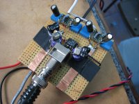 diff amp overkill above.jpg322.4 KB · Views: 276
 -
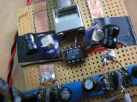
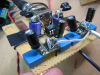 diff amp overkill close 2.jpg261.3 KB · Views: 274
 -
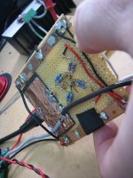 diff amp overkill underside close 2.jpg284 KB · Views: 264
 -
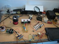 totally perforated mosfet rig.jpg312.3 KB · Views: 75
 -
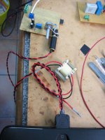 traffo LOD.jpg280.9 KB · Views: 95
 -
 totally perforated.jpg328.5 KB · Views: 79
 -
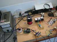
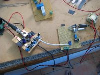 diff amp overkill and sine amp focused.jpg330.8 KB · Views: 71
 -
 diff amp overkill very close.jpg311.1 KB · Views: 87
for those interested, input opamps are lme49710 running on 10v rails and each rail decoupled with 100uf pana fc, 4.7uf x7r ceramic and 100nf polypropylene. second stage is an lt1028 also running on 10v rails decoupled with 180uf sanyo oscon sp, 100nf rifa smd pps caps and 220pf cde silver mica. the 'ground plane' is made with several layers of copper shim/foil and the rails are 8awg goertz copper ribbon. gain network is comprised of plain vanilla 1% metal film resistors matched by hand and using 2 in parallel for each position, i ended up with better than 0.01% matches. overkill for sure, but i didnt want to take any chances this time and its all from my parts bin anyway
btw i realize the decoupling/reservoir stack on the lt1028 would probably have been better up the other way around, with the faster caps at the bottom with shorter lead length to the rail and ground, but it was just easier and more stable (physically) this way.
Last edited:
Hi qusp,
I'm at the stage of build that i just need to put in the transistors and see if it runs.
your circuit is just what we need....
but i have a couple of questions for you:
What specific film caps did you use for coupling the two stages ?
Were you able to use the HP3400A ( i also have one ...) after putting them in ?.
Thanks for your commitment.
Briliant idea
going to give it a go and report back time permitting.
I am not familiar with OPA is 0R0 on the gain brances ?
LT1028 I know a bit beter if DC offset is a problem trim pot to adjust works vell you could reduce resistor noise by going down to 33r and 3k3
LT likes to run hot and you have very large impedence on load (The meter)
But this is just to get the least noise so no mather realy.
What about themperature as VGS change a fair bit if you have a few to test sink and work shop temperature will go up in time.
Hi qusp,
I'm at the stage of build that i just need to put in the transistors and see if it runs.
your circuit is just what we need....
but i have a couple of questions for you:
What specific film caps did you use for coupling the two stages ?
Were you able to use the HP3400A ( i also have one ...) after putting them in ?.
Thanks for your commitment.
hi, yeah it turned out really quite well in the end, thanks for the comments. so well in fact that i'm thinking about doing it properly and boxing it up, with only parts exposed at the top for a pot (nicer than the one i'm using) and placement for the source and DUT. spend a bit more time on power supply, massive sink for the DUT and possibly a pcb. sure there is lab equipment for much of this, but having something purpose built for the..ermm..purpose is more ideal, can be more compact and costs less.
i used what i had at hand; for coupling to the buffer input i used a low leakage 1uf rifa PHE 840m polypropylene X type box cap, probably could have gone lower even (i actually ended up using lme49710, no reason and opa1611 would have been perfectly fine and is cheaper)
the type used across the AC lines and for coupling the buffer to the diff/gain stage i used a 4.7uf rifa pps box film cap, as a 4.7u pps is purpose built for filters like this and is more compact than the first cap i tried, a vcap haha. this one has to be reasonably high capacitance to avoid filtering the 1khz sine when in series with the feedback network and causing less vrms at the output. the rifa smr15 is more stable than pet type wima caps also.
i would not recommend an elco here, i tried rifa peh169 and the leakage was unacceptable
yeah after adding the second filter it was possible to use the hp no problem, but in the end i ended up using my fluke, as once the gain was added it was within the sweet spot for accuracy with this meter and the hp although more accurate at low range, proved problematic to read the values accurately at the 3v scale, where the fluke gives me 3 decimals, meaning 1/100th of a mv after/100.
so if you want to use the hp, adjust the gain so that your measurements will use most of the swing of the readout, or use the dc output on the back into an ADC eg. a nice sound card, which is what i will do once i case it up so i can sit it next to my mac
one thing, make sure that you take the output from the bottom of the output pin of the diff amp, or otherwise outside the feedback loop, i found that connecting the probe to the top of the pin gave bad results and moving it around on the pin a fraction of a mm caused the measurement to vary widely.
let me know how you go
Briliant idea
going to give it a go and report back time permitting.
cool that would be good for someone else to try it
I am not familiar with OPA is 0R0 on the gain brances ?
oh that is just a potential place to also add gain to the input stage, thus the dotted line, i stuck with unity, so its not used in my build. the opa1611 is quite a nice unity gain opamp, that some say is a repackaged opa211, its a fairly low voltage, very low noise unity gain stable jfet input opa, its designed for audio
LT1028 I know a bit beter if DC offset is a problem trim pot to adjust works vell you could reduce resistor noise by going down to 33r and 3k3
LT likes to run hot and you have very large impedence on load (The meter)
But this is just to get the least noise so no mather realy.
yeah its a great chip (and yes i actually think it sounds pretty damn good too), i considered pots before i installed the caps, but as the offset was asymmetrical, i wanted to explore ways to retain the impedance as close as possible on the gain branches.
if absolute accuracy and linearity was first in my mind i may have explored this further, but more important to me here was relative accuracy, so noise is not as great a concern. pin 5 isnt really meant for nulling the degree of offset that was present, its mainly for nulling the small input offset of the amplifier due to operating conditions and with this amount of offset at the inputs it would still likely build up and cause false readings
What about themperature as VGS change a fair bit if you have a few to test sink and work shop temperature will go up in time.
yep i found this out early on, as with this setup being quite resolute, change in temp of the sink, and breeze etc can alter the readings. its a bit unavoidable to have this effect the readings to some degree, but basically i combatted it by using a fairly large sink for the job, timing each measurement and taking the reading at the same point each time (3 minutes after the operating point of 21vds was reached) and then when readings started to make an upward trend (downward vgs trend) i stop and let the sink cool again for a while and use another sink the same.
all measurements done late at night at around the same time when its quite cold and warm the sink up for a few minutes before taking the first reading. otherwise i was getting crazy good unbelievable gm of 0.952s!! once the readings start to spike its quite dramatic, so easily noticeable, because an increase of 0.1mV vgs, means a difference of 10mV at the output. this is something to explore keeping devices this cool perhaps. normal for the chosen fet for this build is pretty amazing already, standard correct readings at this operating point are around 0.91-93s thats why we chose it
Hi Qsp
Hope you dont mind if I mention this on My F5 tread (let me know)
For temperature (and would realy apreciate your wiew)
I have posted a simple circuit to keep themperature of my test rig whith in + - 1 C
bit fidly to adjust pot but once you got it it stays there
I am running 2 amps at 26 volts and temperature set at 50 C (gives me less variation with different ambient conditions)
I have posted on the
MY F5 tread let me know if you need more details.
Al
no thats fine, i'll go check it out. for sure i'll have a look at that for the next update of the rig to case up, but for this job i had already spend an inordinate amount of time/money and results were quite consistent, it was just a pita as far as my time due to having to be quite slow, work late at night and take breaks. doing it late at night in the cold with a largish sink gave me a larger window without actively controlling the temp of the sink; which of course is the next logical step.
oh and of course i meant to say upwards vgs change with higher temp above; while lowering the gm reading
oh and of course i meant to say upwards vgs change with higher temp above; while lowering the gm reading
- Status
- This old topic is closed. If you want to reopen this topic, contact a moderator using the "Report Post" button.
- Home
- Design & Build
- Equipment & Tools
- mosfet gm matching under D1 IV operating conditions