I've been working, for over a month now, on building a Wallin Jig and getting it to work with Speaker Workshop. I've managed to overcome problem after problem, but the latest one has me stumped.
The instructions/tutorial on Eric Wallin's web page describe sending output from the sound card directly to the jig, however, they say that an external amplifier is optional. I have tried 3 sound cards in 2 different computers, and have not found 1 which can come close to 2.83 volts across 8 ohms. They are all line level out (~0.15V) The specific sound card Eric Wallin used is no longer available. Furthermore, after some searching on the internet, it seems the only sound cards capable of speaker level outs are expensive (~$200). This leaves me with the use of a receiver for speaker level voltage.
I connected an inexpensive Insignia receiver as per Wallins' instructions and was able to set the output level to get ~2.83 volts across the 8ohm resistor as instructed. However, when I attach "microphone in" on the sound card to J2 on the jig (left line-level out), while the receiver outputs are connected to BP1 & BP2 (speaker level in) I get a high frequency (~2kHz, 1.6VAC) output from the receiver. This is always present, not just when I'm using SW to generate a tone or recording. If I disconnect the soundcard's MIC IN from the jig, I measure no AC voltage across either the receiver's speaker terminals nor the soundcard's MIC IN signal & ground. Same thing if I connect the soundcard's MIC IN but disconnect the receiver. This only happens when both receiver speaker OUT and soundcard MIC IN are connected.
I should also mention that I checked all resistances on the completed jig according the instructions and everything is spot on. I also noticed that there have not been any posts about the Wallin jig on this forum since 2007.
So my questions are:
1. Does anyone have any ideas?
2. Is the Wallin Jig with Speaker Workshop obsolete? Did it ever work? Is that why so few people are using it?
3. Should I give up and buy the Dayton Audio WT3 with scale for $100? I already have the Dayton microphone&phantom power.
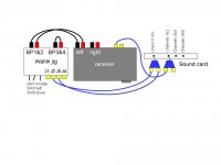
can you draw or post a picture of what is connected to what?
There is no need for 2.83Volts depending on what you are doing - in fact, more than 2-3 volts may blow your soundcard inputs unless you are using the L-pad in the jig. I have tested T/S with regular onboard soundcard outputs - less than a tenth of a volt.
Microphone input on the soundcard is not what you want - you want to use the line in. The mic in is mono and the line in is stereo. The mic input should be muted. It is very important that you go through the level set procedures very carefully.
The tone you are getting is a bit puzzling - could be feedback, what is your soundcard? You could check if it has a "monitor input" checkbox in the settings, and this should probably be off.
my setup
Hi Ron,
Thanks for helping. I switched from using the microphone to using line-in to record and the noise went away! So thank you for that! My problem now, is that, as long as the output from the receiver is near 2.8 VAC, the microphone input clips. I believe the clipping is due to the line-in input instead of the soundcard out or receiver because it lessens as I lower the slider on the line-in control. However, even with the slider all the way down, there is still some clipping. I can eliminate clipping by reducing receiver output (either within SW, the computer's volume control, or the receiver's volume control), but then I'm not measuring with 2.83 VAC across my speaker. I really want to measure with 2.83VAC because 2.828 is such a widely-used standard, and I want my data to be consistent with that of everyone else. I'm also afraid the T/S parameters will change with voltage. We know that the sound of a speaker changes with volume. I'm thinking of increasing the value of R2, the 1175K ohm resister between BP1 and J2, but I don't know if the value 1175Kohm is somehow important for the software. I think you mentioned an L-pad in your reply. My plans don't call for a variable resistor in the jig.
Hi Ron,
Thanks for helping. I switched from using the microphone to using line-in to record and the noise went away! So thank you for that!
My problem now, is that, as long as the output from the receiver is near 2.8 VAC, the microphone input clips. I believe the clipping is due to the line-in input instead of the soundcard out or receiver because it lessens as I lower the slider on the line-in control. However, even with the slider all the way down, there is still some clipping. I can eliminate clipping by reducing receiver output (either within SW, the computer's volume control, or the receiver's volume control), but then I'm not measuring with 2.83 VAC across my speaker. I really want to measure with 2.83VAC because 2.828 is such a widely-used standard, and I want my data to be consistent with that of everyone else. I'm also afraid the T/S parameters will change with voltage. We know that the sound of a speaker changes with volume. I'm thinking of increasing the value of R2, the 1175K ohm resister between BP1 and J2, but I don't know if the value 1175Kohm is somehow important for the software. I think you mentioned an L-pad in your reply. My plans don't call for a variable resistor in the jig.Attachments
Try without the receiver until you get things working. You may need to adjust the output level in SW.
Review Eric's site
Eric Wallin's Internet Homepage
very carefully, he goes into clipping in some detail.
I think 2.83V is overkill for T/S and probably not even warranted for SPL measurements, at least until you get things going. You can sometimes fry a tweeter with not much more in pure sine wave power.
The jig can be overcomplicated to use at times, I made a simpler one without all the protections, but I don't need a cheat sheet to use it.
OK. Thanks Ron. I agree that the jig is overly complicated and difficult to build. If I were to do it all over again, I would remove the 8 ohm 20W resistor and use it externally. I'll take impedance measurements at <8.3VAC, and I should still be able to do SPL measurements at 8.3VAC. You made a good point about frying a tweeter, because it won't have a high pass filter protecting it from lows. I had not thought of that! You may have saved me a tweeter!
You may have saved me a tweeter!I'll take impedance measurements at <8.3VAC, and I should still be able to do SPL measurements at 8.3VAC.
Thiele and Small parameters are intended for small signals: for sure 8.3 VAC, as well as 2.83 VAC, are not small signals.
The use of an amplifier in impedance measurements, instead of a line level output, is mainly due for impedance matching, not for unsufficient output level.
Regards,
Claudio
The WT3 is ideal for quick T/S measurements, but is useless of course for SPL. You say you want your measurements to match those of others, but have you actually found people who do T/S @ 2.8V? Try with lower voltages first, once you're sucessful there, only then move on to tweeter destroying voltages if you must. I always use an amp with my Wallin as I know my various sound cards are line level out. If you're clipping inputs, turn it down or use the attenuation features of the jig.
Once you get the speaker built you can put on your "If it's too loud you're too old" tshirt and crank it up to the neighbor's displeasure, until then take it easy until you get the hang of it.
D'Appolito in his "Testing Loudspeakers" book recommends using as low a level as you can get away with while still providing reliable results for T/S measurements.
Good luck, measurement is a pain.
I thought everyone was measuring T/S parameters at 2.84 VAC! I thought it was industry standard! I'll play around with measurements at different voltages. I also just assumed that WT3 could do SPL measurements. It's such common sense. Why wouldn't the designers include it? Now you guys have saved me from wasting $100 on software I don't need, and saved me from destroying a tweeter (a $54.00 Vifa). And I think I'll buy myself a book. This forum is awesome. You guys are great.
I have used as much as 2Vac applied to a series combination of 8ohm speaker and 1k0 resistor.
The speaker sees only mVac.
I was listening to Radio3 today. The average level at the speaker terminals was varying between 50mVac and 100mVac. Yes, less than 1mW for listening averages. I have Radio Forth on just now. Average levels are 200mVac to 400mVac.
The speaker sees only mVac.
I was listening to Radio3 today. The average level at the speaker terminals was varying between 50mVac and 100mVac. Yes, less than 1mW for listening averages. I have Radio Forth on just now. Average levels are 200mVac to 400mVac.
Last edited:
I thought everyone was measuring T/S parameters at 2.84 VAC! I thought it was industry standard! I'll play around with measurements at different voltages. I also just assumed that WT3 could do SPL measurements. It's such common sense. Why wouldn't the designers include it? Now you guys have saved me from wasting $100 on software I don't need, and saved me from destroying a tweeter (a $54.00 Vifa). And I think I'll buy myself a book. This forum is awesome. You guys are great.
The WT3 seems designed to be as simple as possible, USB on one end and two alligator clips on the other. It takes longer for my stupid XP laptop to boot than it does to plug the WT3 in and take a T/S and impedance measurement. So it has it's uses. I got mine free though (a raffle at a DIY event.)
I'd pay some good money for a single simple unit that plugged into USB, came with a calibrated mic (on a long cord), and then a connection to the speaker (amplified so probably need a power connection too (other than USB)). That would make measurement so much less of a chore. Otherwise get out the PC, mic preamplifier, mic, amp, wallin jig, sound card and a pile of cables
DON'T connect J4 to mic input on soundcard...
I realize this is an old thread, but for those who haven't figured it out by now, DON'T connect the J4 input to the sound card mic input. It sounds like the original poster did that. J4 is for an external microphone. It is not meant to connect to the sound card's mic input. Usually you need a measurement mic run into a mixer or phantom power device. Then you run a line-out from that device to the J4 on the jig.
Just thought I'd post in case someone comes across this old thread and is confused about the mic jack vs. J4 on the jig.
And as others mentioned, get those record levels set properly. Set your receiver volume to 1 or 2, and the Windows record mixer line-in all the way up. As mentioned in setup routines, record a sine wave and monitor the left and right "in.l" and "in.r" graphs. Change the Windows mixer sound level until sine waves don't clip. As a side note, sine waves should measure around +16k/-16k. MLS signals will be about +/-22k at this level. Click "view-vu meter" on the menu to monitor this.
Good luck to all.
- Status
- This old topic is closed. If you want to reopen this topic, contact a moderator using the "Report Post" button.
- Home
- Design & Build
- Equipment & Tools
- About to give up on Wallin Jig & Speaker Workshop