Would you recommend others try this at home without a properly insulated EHT probe?I have measured signals as high 10kv acurately with my scope using a proper resistor divider...
It was ment as an example of how to measure a higher voltage than what the maximum input rating is, inculding the 10X probe.
I am not refering any one to try to measure the output of a neon transformer with this method.
"Also I would like to use the scope to measure some mains voltage LED drivers I put together"
And I supose this would safe for the average noob as well?
Do you know what will happen if one tried to connect the ground clip of the probe to the wrong side of the line? jer
Last edited:
hehehe, but those probes cost twice as much as the scope.... I think i'm lucky getting the 600V probes free too. Yes I believe connecting the ground could bring the scope enclosure up to the rectified mains voltage that I'm measuring. I realy want to learn more about how to possibly issolate things with a transformer if someone can assit, I have a pair of bulky 24V transformers.
[book=I am not refering any one to try to measure the output of a neon transformer with this method.
[book=
I have measured neon transformers (with ufarad caps across the output to boost the voltage even more) with resistive dividers on DVMs as well as scopes. You need to make the dividers with strings of resistors to physicaly spread out the voltage and then cover the whole thing with HV insulation. SAFETY is a major concern, but it is doable.
The ground of the scope probe will probably be connected to the power plug ground (third pin) so the enclosure will not become hot, the probe will ground
whatever you connect the probe ground to. Isolating the scope thru a transformer is lifting its ground and is DANGEROUS. The proper way to measure across a device thats hot on both ends is to use 2 probes and use the A-B function on the scope, which shows the voltage diff between the 2 probe tips.]%[/book]]%[/book]
[book=
I have measured neon transformers (with ufarad caps across the output to boost the voltage even more) with resistive dividers on DVMs as well as scopes. You need to make the dividers with strings of resistors to physicaly spread out the voltage and then cover the whole thing with HV insulation. SAFETY is a major concern, but it is doable.
Yes I believe connecting the ground could bring the scope enclosure up to the rectified mains voltage that I'm measuring. I realy want to learn more about how to possibly issolate things with a transformer if someone can assit, I have a pair of bulky 24V transformers.
The ground of the scope probe will probably be connected to the power plug ground (third pin) so the enclosure will not become hot, the probe will ground
whatever you connect the probe ground to. Isolating the scope thru a transformer is lifting its ground and is DANGEROUS. The proper way to measure across a device thats hot on both ends is to use 2 probes and use the A-B function on the scope, which shows the voltage diff between the 2 probe tips.]%[/book]]%[/book]
At any rate, there are proper commercial 100x and 1000x scope probes available.
This Fluke high voltage probe allows a multimeter to measure up to 40,000V though AC or DC Overvoltage Category I available from Mouser for $172.98

80K-40 Fluke Test Probes
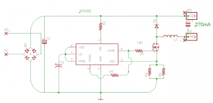
Thanks for the advice so far, I know its hard without seeing the schematic. Please ignore the ground, I just used it to pour a plane, to sink heat into. There is only the two ac wires comming in. It can operate from 85 to 265VAC. On the output side it puts out an unisolated 373VDC with no load, and 42VDC with the LED connected.
I would like to safely check the PWMD signal to the FET to see how close it is comming to calculations. I also want to check for noise and osilations if possible. Sadly I'm also waiting for an inductor until May apparently, the one I have now works, but is not very efficient as it drives the frequency up to 100k in stead of the 70k or so I want. I now found the largest inductors that would fit our application without going custom made.... just waiting for it. The scope and inductors should land at the same time, so I want to be ready before the time.
I would like to safely check the PWMD signal to the FET to see how close it is comming to calculations. I also want to check for noise and osilations if possible. Sadly I'm also waiting for an inductor until May apparently, the one I have now works, but is not very efficient as it drives the frequency up to 100k in stead of the 70k or so I want. I now found the largest inductors that would fit our application without going custom made.... just waiting for it. The scope and inductors should land at the same time, so I want to be ready before the time.
Attachments
It's O/T, but it is easy to make and adequately calibrate your own inductive clip probes that can safely supply isolated,
low voltages for use on a scope in differential or grounded mode. Junkbox tiny ferrite SMPS transformer cores, with just
tens of turns could be ideal. We need to be certain of using sufficient insulation and making sure it can't move or fail by
poor construction. However, it's the same principle as clamp DMMs, so nothing new.
There are, or were, tons of junked network BNC coax cables, dummy loads and adaptors suitable as CRO leads. Keep an eye out.
For those getting a first scope try finding one that has an on screen measurement system.
This feature is exteremly handy for quick and use full measurements.
Although mine does not have the higest level of resolution but it sure beats having to have a meter hooked up at the same time and takes the strain out of eyeballing and geusstimating the graticule. jer
This feature is exteremly handy for quick and use full measurements.
Although mine does not have the higest level of resolution but it sure beats having to have a meter hooked up at the same time and takes the strain out of eyeballing and geusstimating the graticule. jer
For those getting a first scope try finding one that has an on screen measurement system.
This feature is exteremly handy for quick and use full measurements.
Although mine does not have the higest level of resolution but it sure beats having to have a meter hooked up at the same time and takes the strain out of eyeballing and geusstimating the graticule. jer
Yes, I fully agree with that. The on-screen readout of amplitude and frequency are extremely convenient features.
OWON-Meet your best needs
I'm getting the PDS5022S, can you tell from this sheet if it can do that on screen display? It does have realtime USB data transmission, so I guess measurments could be displayed on the PC....
Second link is the manual, only 668KB.
http://www.ageta.hu/pdf/pds5022s.pdf
I'm getting the PDS5022S, can you tell from this sheet if it can do that on screen display? It does have realtime USB data transmission, so I guess measurments could be displayed on the PC....
Second link is the manual, only 668KB.
http://www.ageta.hu/pdf/pds5022s.pdf
Last edited:
I bought a 40Meg Owon at he last place I worked at, it feels a bit cheap compared to the Tek scopes I used elsewhere, but I thought it good value for money.
Couple of little things, the screen has a narrow viewing angle and the math functions are a bit funny, if you change the resolution the readings change, so you have to avoid changing the resolution in those circumstances. This is a software issue, maybe they fixed it by now.
Here's what I wrote at the time:- http://www.diyaudio.com/forums/parts/147603-owon-pds-6042s-oscilloscope-review.html
w
I have a 60MHz Owon handheld, their HDS2062M-N, which is a pretty decent scope. The FTT mode is particularly good for an inexpensive 'scope, and it has a wide assortment of automated parameter measurements.
The multimeter mode is a bit silly with sometimes sluggish response; but the 'scope is very nice. It does, like most DSOs, use 8-bit DACs so all the dynamic range issues (48dB at best) apply.
The multimeter mode is a bit silly with sometimes sluggish response; but the 'scope is very nice. It does, like most DSOs, use 8-bit DACs so all the dynamic range issues (48dB at best) apply.
This Fluke high voltage probe allows a multimeter to measure up to 40,000V though AC or DC Overvoltage Category I available from Mouser for $172.98
80K-40 Fluke Test Probes
I bought five or six of those Fluke 80K-40 probes at a mil-surplus auction, once, brand new, WITH current calibration stickers, for way less than one goes for now. I still have two of them. But one is missing its screw-in tip (was missing when I bought it; it's about like a soldering iron tip). They are BIG.
For scopes, I think the Tektronix P6015 probe was the 1000x 15kV one. A few of those passed through here, too, and even a can of the dielectric fluid they get filled with in order to work up to their full rated voltage. They might still be on ebay once in a while. Sometimes they weren't too expensive. But there are 100x probes that are far cheaper, I think, that might go up to 5000 Volts.
And there are lots of multimeter probes that go up to 5000 Volts, that are quite inexpensive. I probably still have lots of them, actually, from a large lot of multimeters that I bought, once, that all came with hard suitcases and accessories (Fluke 467 maybe?). [Please note that I am no longer in the business.]
Yes, Cliff, thanks I read similar reviews, seems like it can be fixed with the V1.7 firmware. I believe I have quite a learning curve that I could probably fit into the parameters this scope covers.
Could you explain where the 48db thing would come in analysing small electronic audio projects like say a headphone amp or a small class B. Like what would I be testing/looking at when I experience this limit as negative.
Gotee I need to get into your will it seems.
BTW, I saw most probes come in multiples of 10, i.e. x10 x100 x1000, now the probes I'm getting with the scope are apparently rated for 600V, would that just be a n insulation rating or is there also a voltage reduction takeing place in the probe? It would work out to something like 20x, I only see settings for 10, 100 and 1000 in the manual... feeling a bit confused.
Last edited:
- Status
- This old topic is closed. If you want to reopen this topic, contact a moderator using the "Report Post" button.
- Home
- Design & Build
- Equipment & Tools
- Any point in buying a scope for audio work?