I have 2 identical unknown transformers that I'd like to wire back to back to make an isolation transformer. They are both from the same model UPS (battery back up) and I haven't been able to find ANY information on them (markings include 430-2060B; E184736; DV-130-1). Since they are the same, I'm not worried about getting a 1:1 ratio. My question is, can I hook up all the different windings back to back, or should I just use a single winding? I haven't measured the voltages yet, but I have 3 large wires on the output side that are Red, White, and Black. My thought is: MAINS (110v) ---> xfmr1 Input --- xfmr1 Red Output ---> xfmr2 Red Input --- xfmr1 White Output ---> xfmr2 White Input --- xfmr1 Black Output ---> xfmr2 Black Input --- xfmr2 Output (110v)
Does this sound right?
Thanks!
Does this sound right?
Thanks!
Hmmmm... interesting to think about.
It should work IF you get the phase correct.
You might get some bucking because of slight phase differences between the sets of windings. That being due to the variance in inductance and interwinding capacitance.
I'd fire it up first with just the heaviest windings connected, and use a LOW voltage xmfr as the source (like 12vac) and see what the output looks like compared to the input. Then try it the same way with the rest of the windings. Finally, try it with some sort of current limiting (a lightbulb for example - or a variac with ammeter) on full mains power.
I doubt that any voltage will be lost, but some power may be eaten up in the xfmrs, but who cares...
_-_-bear
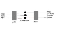
MM, Here is a hastily drawn diagram in Paint. I'm not too worried about voltage loss, as this will be (Before???, After???) my variac.
Bear, I'm not sure which windings are the heaviest, as all three wires shown are the same gauge. Could it be center-tapped? If so, would it damage anything if hooked up as shown in the diagram?
Thanks Moose and Bear! Lot's of animals around these parts....
Bear, I'm not sure which windings are the heaviest, as all three wires shown are the same gauge. Could it be center-tapped? If so, would it damage anything if hooked up as shown in the diagram?
Thanks Moose and Bear! Lot's of animals around these parts....
Attachments
So I finally had a chance to actually test the transformers in question. Both tested the same, and all results were at 60hz with 110V in.
Red-White: 15.7vac
White-Black: 7.85vac
Red-Black: 7.85vac
Blue-Brown: 19vac
I didn't mention the blue/brown wires before as they are quite small compared to the rest so I'm not planning on using them no matter what.
So what's up with different values between the first three sets of wires? Can I still use this as an isolation setup? Help and thanks!
You have a 7.5-0-7.5 volt transformer I guess allowing for mains variations (otherwise a 0-15 volt with a centre tap - same thing)
connect the red and white on one to the red and white on the the other and insulate the centre tap wires.
That will work fine. Will work as back to back transformers at the full power rating
connect the red and white on one to the red and white on the the other and insulate the centre tap wires.
That will work fine. Will work as back to back transformers at the full power rating
Spiny, thank you! That worked! I measured 110vac in and just a little less on the output (with 2 multimeters).
Next question, can I (or do I want to) connect the smaller wires in the same way to get a little extra capacity? Seems a shame to have an unused coil just going to waste.
Thanks!
Next question, can I (or do I want to) connect the smaller wires in the same way to get a little extra capacity? Seems a shame to have an unused coil just going to waste.
Thanks!
")
- Status
- This old topic is closed. If you want to reopen this topic, contact a moderator using the "Report Post" button.
- Home
- Design & Build
- Equipment & Tools
- Isolation Transformer (multi-winding transformers)