Image heavy thread warning!
Here is a power source I made for testing the circuits in my upcoming transistor tester, especially calibrating the difference amplifiers. My bench power source has a 3/4 turn pot for 0-40V . . . not good for fine control even with a "fine" control adjustment.
The goals were:
The result: at least 6A of fairly-quiet low voltage DC with 10-turn control up to 1.999V. Output voltage indication with 1mV resolution. Total success. It only *looks* like an unworkable bodge!")
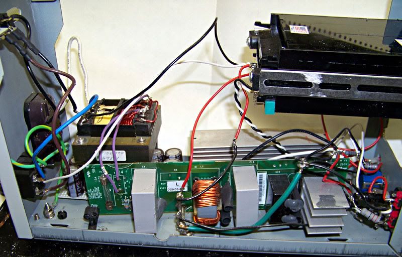
The mains power comes in to the supply filter I got from an old server power supply. I had to remove a thermistor that is less of a problem for a wide-input switcher than for a low-voltage linear supply. Jumpering out the thermistor gave me instant high current capacity.
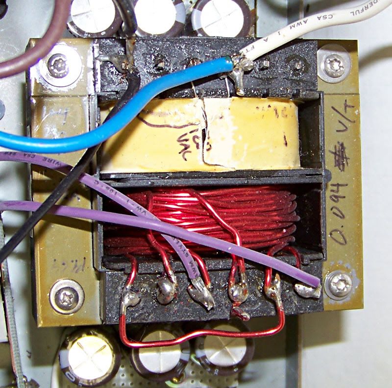
Then it's off to a transformer I snagged from a piece of medical equipment and rewound for the voltages I needed. It ended up with three secondaries with just a few dozen turns each of 16AWG magnet wire, which are wired in parallel. I put kapton tape between the layers of the windings and pulled each turn tight with the aid of a bench vise. It is pleasantly silent in operation.
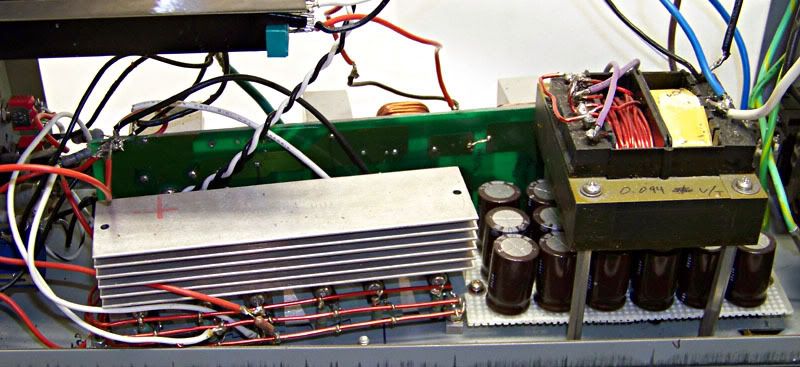
Then back to the filter PCB for rectification. From there it's off to a bank of capacitors in parallel for about 0.12F. This sits at almost exactly 5VDC. The circuit is pretty basic: A value-faked Bourns 10-turn pot sets the base voltage of a 2N6045, which feeds eight 2n4918 transistors their base current. These are mounted to a heat sink that also came from a computer power supply. The bus bars are more 16AWG magnet wire. The output transistors are wired in parallel and have 0.22 ohm resistors to help share the current load between them.
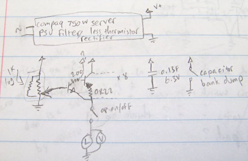
Unless the project is VERY complicated, I tend to work from a rough idea and refine the details in my head. Behold the working drawing:
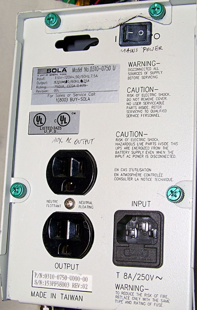
The case used to house a Sola brand UPS which died and had its guts sent off to the recyclers. It has a power outlet on the back, and I had power going in, so I figured "why not" and now there's an auxiliary mains power outlet on the back of my power supply.
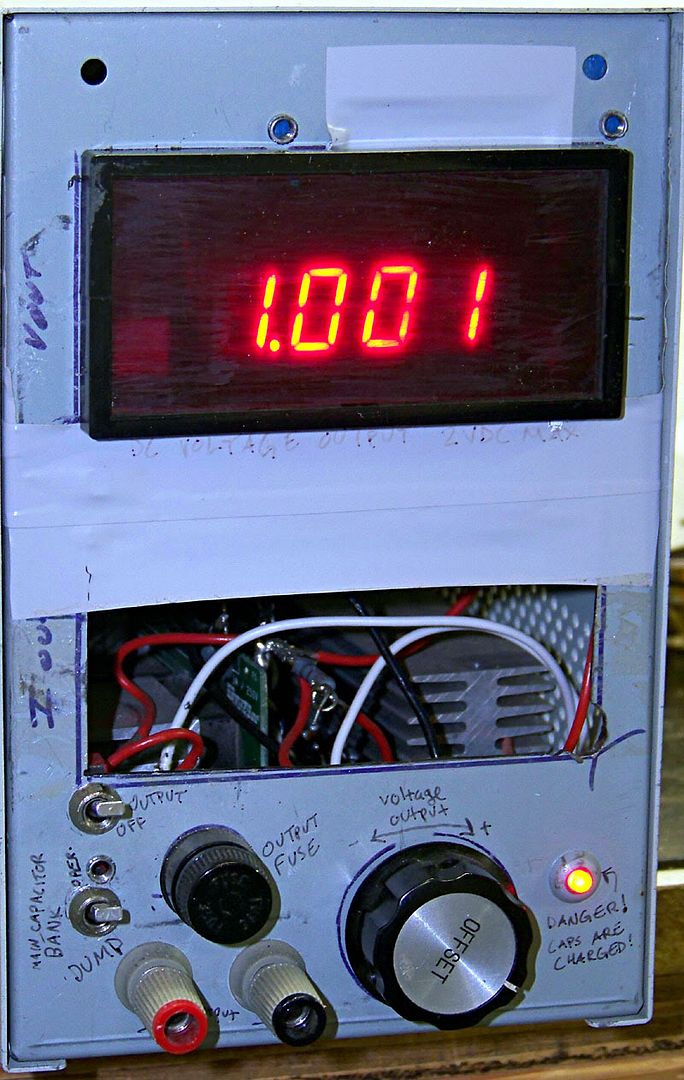
The otuput voltage meter is a positively ancient 3.5 digit panel meter the brand of which I forget. At work we had to replace it because it was missing the red diffuser . . . at a cost of $250 to the customer. It is a type of meter made by everyone who does instrumentation. The case was damaged in addition to the missing diffuser, so I replaced it with a case from an Omega thermocouple readout acquired separately, years later. These things are amusingly ubiquitous and work great. This one was calibrated against my bench meter from work, and they agree perfectly so I called it good enough. There was going to be a second meter for current output, but it ended up being both more than zero effort AND interfering with the filter PCB, so for now there's a hole in the front panel. Don't stick your hand in there. The knob is from an Olympus wafer inspection microscope station and the binding posts came from an HP analog RMS voltmeter.
Safety: The mains input is switched and fused, the output is fused, and there is a switch to turn off the output. Because even at 5V, 0.12F is a lot of potential, I also installed a lamp to show that the caps have a charge on them, and a switch with a power resistor to bleed off the caps in under half a minute.
This is version two. In the first version, I killed the output transistor (singular) with 20VDC on its base, which prompted me to roll the new transformer. Then I figured out the inrush current-limiting thermistor was fighting me too hard and removed it . . . AFTER I upgraded everything else for high current output.
If I were to do it again, I would put a current meter in, and consider fine/coarse voltage controls and a current limit of some sort. As is: this was a means to an end and it does the job, so there it is.
Here is a power source I made for testing the circuits in my upcoming transistor tester, especially calibrating the difference amplifiers. My bench power source has a 3/4 turn pot for 0-40V . . . not good for fine control even with a "fine" control adjustment.
The goals were:
- Precision output voltage control
- Up to 2VDC out
- High current capacity
- Metered output
The result: at least 6A of fairly-quiet low voltage DC with 10-turn control up to 1.999V. Output voltage indication with 1mV resolution. Total success. It only *looks* like an unworkable bodge!
An externally hosted image should be here but it was not working when we last tested it.
The mains power comes in to the supply filter I got from an old server power supply. I had to remove a thermistor that is less of a problem for a wide-input switcher than for a low-voltage linear supply. Jumpering out the thermistor gave me instant high current capacity.
An externally hosted image should be here but it was not working when we last tested it.
Then it's off to a transformer I snagged from a piece of medical equipment and rewound for the voltages I needed. It ended up with three secondaries with just a few dozen turns each of 16AWG magnet wire, which are wired in parallel. I put kapton tape between the layers of the windings and pulled each turn tight with the aid of a bench vise. It is pleasantly silent in operation.
An externally hosted image should be here but it was not working when we last tested it.
Then back to the filter PCB for rectification. From there it's off to a bank of capacitors in parallel for about 0.12F. This sits at almost exactly 5VDC. The circuit is pretty basic: A value-faked Bourns 10-turn pot sets the base voltage of a 2N6045, which feeds eight 2n4918 transistors their base current. These are mounted to a heat sink that also came from a computer power supply. The bus bars are more 16AWG magnet wire. The output transistors are wired in parallel and have 0.22 ohm resistors to help share the current load between them.
An externally hosted image should be here but it was not working when we last tested it.
Unless the project is VERY complicated, I tend to work from a rough idea and refine the details in my head. Behold the working drawing:
An externally hosted image should be here but it was not working when we last tested it.
The case used to house a Sola brand UPS which died and had its guts sent off to the recyclers. It has a power outlet on the back, and I had power going in, so I figured "why not" and now there's an auxiliary mains power outlet on the back of my power supply.
An externally hosted image should be here but it was not working when we last tested it.
The otuput voltage meter is a positively ancient 3.5 digit panel meter the brand of which I forget. At work we had to replace it because it was missing the red diffuser . . . at a cost of $250 to the customer. It is a type of meter made by everyone who does instrumentation. The case was damaged in addition to the missing diffuser, so I replaced it with a case from an Omega thermocouple readout acquired separately, years later. These things are amusingly ubiquitous and work great. This one was calibrated against my bench meter from work, and they agree perfectly so I called it good enough. There was going to be a second meter for current output, but it ended up being both more than zero effort AND interfering with the filter PCB, so for now there's a hole in the front panel. Don't stick your hand in there. The knob is from an Olympus wafer inspection microscope station and the binding posts came from an HP analog RMS voltmeter.
An externally hosted image should be here but it was not working when we last tested it.
Safety: The mains input is switched and fused, the output is fused, and there is a switch to turn off the output. Because even at 5V, 0.12F is a lot of potential, I also installed a lamp to show that the caps have a charge on them, and a switch with a power resistor to bleed off the caps in under half a minute.
This is version two. In the first version, I killed the output transistor (singular) with 20VDC on its base, which prompted me to roll the new transformer. Then I figured out the inrush current-limiting thermistor was fighting me too hard and removed it . . . AFTER I upgraded everything else for high current output.
If I were to do it again, I would put a current meter in, and consider fine/coarse voltage controls and a current limit of some sort. As is: this was a means to an end and it does the job, so there it is.