I've just finished updating Reg Williamson's greening of the IG-18. With just a handful of parts, I'm happy to say that performance is significantly better than stock and along the way I found that some changes for the better are slightly counter-intuitive and different from Reg's experience.
While a major replacement of the guts can yield an outstanding oscillator (see IG-18 #2 -- simple changes can give very good performance.
I've got 0.007% THD at 1kHz with feedback set for a 5V output, and about twice that for 10V out, with good stability at all frequencies. It's here for those interested:
IG-18 #1
Would you like to take a crack at Heathkit's lesser-known audio generator, the IG-1272? Uses a JFET along with three incandescent lamps, and has a bipolar supply, but seems generally similar to the IG-18. My measurements suggested distortion is down around .02%.
(Waves atcha from the east side of Puget Sound)
(Waves atcha from the east side of Puget Sound)
Last edited:
@ Damon Hill -- I've never seen one. Do you have a pdf of the circuit? 0.02% seems a bit high for an elaborate AGC circuit. I'd love to see the circuit if you have it or can scan it.
I'm about to post some general observations about RC oscillators to my site which rounds up stuff I've discovered trolling around for info. Stay tuned.
I'm about to post some general observations about RC oscillators to my site which rounds up stuff I've discovered trolling around for info. Stay tuned.
At one time there was a schematic online, at Bama I think; some company bought the rights to the manuals and it was taken offline, as I understand.
So, I'll have to see if my old scanner is still working and get something posted this weekend.
It's quite different from the IG-18; all pushbutton and no square wave output, but there is a sync output on the back.
So, I'll have to see if my old scanner is still working and get something posted this weekend.
It's quite different from the IG-18; all pushbutton and no square wave output, but there is a sync output on the back.
This thread reminded me of one of those back-burning projects I have to try: AN43
See figure 47 for a 0.0003% wien-bridge circuit from Jim Williams.
There are also some circuits replacing the integrator with Linear's true RMS converters --
Krohn Hite uses a a FET AGC in their 4400 -- it's the only oscillator which comes close to the Audio Precision. They run from about $300 to $700.
An externally hosted image should be here but it was not working when we last tested it.
@jackinnj -- very interesting spectra -- thanks for sharing. The Audio Precision has very low even order products, while the Krohn-Hite has low odd order. I suspect that the relatively high even order products in the K-H result from residual channel modulation in the AGC FET. Is the K-H a phase-shift/state-variable design, as I suspect?
Does the AP use software generation of the sine wave with a DAC output? If so, then maybe the odd-order stuff is from the output amp, whatever it is.
I haven't put hands on either of these units nor have I seen schematics.... I'm guessing that the roughly 6VRMS output is close to the max for both units, is this the case?
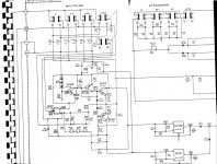
@ Damon Hill -- without seeing the bridge configuration -- I'm guessing here on much of the detail -- I think that, given the equal capacitor values in the multiplier switches, this is a Wien Bridge, in which case the resistors of the bridge arms in the frequency switches have equal values as well. The JFET is the input transistor and is in cascode with Q105 for higher gain and high input Z. The Wien bridge config needs a very high input Z at the amp input due to the large resistors needed for low frequencies.
The three lamps are the only AGC. What I did in the IG-18 may equally well benefit this unit -- raise the emitter resistance of Q102 to 1k and the collector load of Q105 to 10k or 20k, then play with the feedback control. The bootstrapping of Q104 with the 100u cap from the output gives higher output voltage swing, but I think I would give up some output level and use a constant current source, either FET or transistor, as the collector load for Q102, replacing R177 and 178. The 22 ohm emitter resistors for the output devices are a little large for a two-diode bias scheme -- there's a risk of crossover distortion -- might be good to reduce those to 15 ohms each. I'm really confused about why they returned the lamp string via two capacitors to the two supplies, rather than via capacitors to ground -- but returning to the supplies ensures that the caps always have the correct polarity bias; but I can see problems from noise from the supplies getting back into the AGC loop. Better, I think to make a non-polar cap out of 470uF/35V units back to back, and run that to ground.
Finally, ? is there a buffer amp, like an emitter follower, for the meter? If not, this is a must-have for better distortion performance. See my greening page on the IG-18:
IG-18 #1
My 2 cents.
BTW, given the split supplies, this unit is a natural for using a FET-input op-amp like the OPA604 as the gain stage which would make some of the suggestions above unnecessary. Of course, you'll have to lower the supply rails to +/-18V or +/-15V-- I think this would be easy with a change in the resistor values that go from the regulator control pins to ground.
I imagine this unit can do much better than the original design....
No meter buffer, a little detail they left out. I'll build a couple and try them out.
I have a batch of Panasonic 220 uF NP caps originally intended for amplifier feedback, but I could try them in this application.
I'll do a better scan later on, but it'll have to be multipart to get the entire thing.
Always liked the look and build of the later Heathkit gear, back in their days of emulating the HP "look".") I've got both the IM and THD meters, AC meter and the FET meter, which apparently needs some work. Still using my ancient IO-105 scope built back in the early 70's.
I've got both the IM and THD meters, AC meter and the FET meter, which apparently needs some work. Still using my ancient IO-105 scope built back in the early 70's.
I have a batch of Panasonic 220 uF NP caps originally intended for amplifier feedback, but I could try them in this application.
I'll do a better scan later on, but it'll have to be multipart to get the entire thing.
Always liked the look and build of the later Heathkit gear, back in their days of emulating the HP "look".
I've got both the IM and THD meters, AC meter and the FET meter, which apparently needs some work. Still using my ancient IO-105 scope built back in the early 70's.@ Damon Hill -- I'd like to see how the THD meter is similar to and different from the HP 33/334, especially since I'm well into greening a 334 -- just finished wiring up a replacement A3 rejection amp board. A few things left to do, then it's time to see if it works. Do you have the manual for that as well? Let see, was it the 5238? Can't quite rmember.
RE the Panasonic NP caps -- excellent, if they have the voltage rating -- should be 25V or more, 50V would be great.
RE the Panasonic NP caps -- excellent, if they have the voltage rating -- should be 25V or more, 50V would be great.
Here's the amplifier section of the later version of the Boonton 1120 -- works quite well up to ~140kHz -- you would have to beef up the power supply to use it:
Board Layout:
An externally hosted image should be here but it was not working when we last tested it.
Board Layout:
An externally hosted image should be here but it was not working when we last tested it.
- Status
- This old topic is closed. If you want to reopen this topic, contact a moderator using the "Report Post" button.
- Home
- Design & Build
- Equipment & Tools
- Re-greening the Heathkit IG-18