They have soared to €144 in the mean timeand I could not ignore the 400 mOhm.
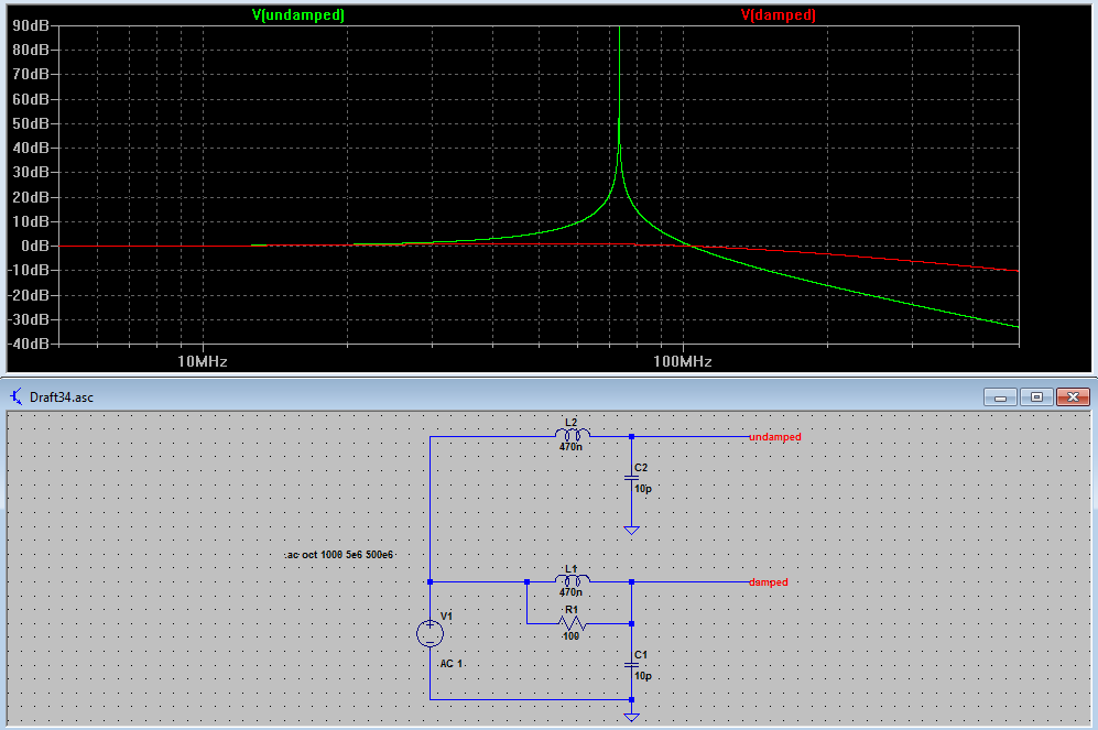
BTW who would think that adding a ferrite bead to an amplifier input
(Würth from LTspice lib) would f* up the loop gain of an amplifier so completely.
Damping it with the 5 Ohms makes everything nice again.
I had the hope that I could get rid of the gate voltage divider / coupling C for
the cascode/bootstrap, but the depletion MOSFET is not depleted enough. It leaves
only 1 V at the drain of the input JFETs.
The opened loop goes from V5 to the output of U4. R14 is a first order approximation
of the feedback divider.
Reproduced with permission from the author. This one, as shown, won't match your noise requirements (is about 0.3nV/rtHz) but can be fed from an unregulated (or LM78xx regulated) power supply, without an additional noise pip, hence virtually no limit of the number of devices you can parallel. Feel free to use the principle if you find it valuable, only careful with the servo pole-zero distributions, they must more or less match/cancel to avoid a LF gain bump. Without the 1mF/1k LF pass of the servo output, the servo LF noise still creeps in the signal chain.
I've tried it myself and it works a treat. Yes, adding a few ohms in parallel with the input inductors is a good idea.
Attachments
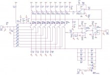
Please tell me R129 is not critical
Can be obviously omitted for a 0.01% total 99ohm.
I had the hope that I could get rid of the gate voltage divider / coupling C for the cascode/bootstrap, but the depletion MOSFET is not depleted enough. It leaves only 1 V at the drain of the input JFETs.
1 volt actually should be OK for the Jfet and its internal heat will be less. I usually get closer to 3V in that configuration. What current are you running the Jfet at? There is a rapid diminishing return as you increase the current. Going above 5 mA usually doesn't get much return but I have not played with that FET in years.
Given the price of the Interfet devices, I feel it is justified to let them sweat
a little bit to get as much from them as possible. I know the sqrt(sqrt()) rule
They'll get a nice Thermalloy cooler anyway, if only to provide a thermal low pass.
As long as a pack of Lithium Ion cells works for some hours, that's OK for me.
The junction capacitance explodes @ 1V; half the C would allow twice
the transistors with a resulting sqrt(2) noise advantage.
It is 20% here, and there, and there; I just want to fathom out how far I get
peeling the onion.
Some other depletion FETs from this week's DigiKey box of wonders seem
to fit better. The Infineon devices have much less spread, that would be
nice for a CCS, but the voltage is quite small for a cascode/bootstrap.
That Locky-Z curve tracer delivers questionable results from time to time,
esp. at low voltage / high current. Weird.
Cheers, Gerhard
(please feel free to correct me if I invent ungrammatical constructions.
It won't get better otherwise!)
Attachments
Last edited:
Yes, adding a few ohms in parallel with the input inductors is a good idea.
Yes, it limits the damage done by the on-board ferrite bead, but an external
undampened inductance still will make the amplifier oscillate. The negative
impedance, when looking into the gate, is still there.
Gerhard, would you care to elaborate?The junction capacitance explodes @ 1V
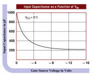
Here is some serious work on modeling the capacitance of gate source and gate drain vs voltage. http://www.iaeng.org/publication/WCECS2016/WCECS2016_pp771-775.pdf
The change is significant (on all semis) and C goes down with voltage. Its also a distortion generating parameter that can't be removed with simple feedback. Cascode is your friend but with 1V and big JFET gates the C is higher. I usually get about 3V with lower current and in this case higher noise. However even though theoretically the noise goes down as you approach 0Vds with the high current fets it doesn't quite hold. One of the standard texts explained the phenomenon but I long ago lost track of the text. A Quantech is really helpful in exploring this. (I need to get mine back from Constellation. . .) Cooling also helps. The big JFET was created for the infrared mapping satellite I was told by Interfet. In that application it was cooled to a very low temperature. But it all may be marketing BS. They also told me they use a 2" semi line. That allowed me to buy a complete waver and have them make custom pairs to my spec. I don't know it they are that accommodating any more.
The change is significant (on all semis) and C goes down with voltage. Its also a distortion generating parameter that can't be removed with simple feedback. Cascode is your friend but with 1V and big JFET gates the C is higher. I usually get about 3V with lower current and in this case higher noise. However even though theoretically the noise goes down as you approach 0Vds with the high current fets it doesn't quite hold. One of the standard texts explained the phenomenon but I long ago lost track of the text. A Quantech is really helpful in exploring this. (I need to get mine back from Constellation. . .) Cooling also helps. The big JFET was created for the infrared mapping satellite I was told by Interfet. In that application it was cooled to a very low temperature. But it all may be marketing BS. They also told me they use a 2" semi line. That allowed me to buy a complete waver and have them make custom pairs to my spec. I don't know it they are that accommodating any more.
The standard textbook technique for suppressing VHF/UHF oscillation dating back before semiconductors was to use a "grid (gate/base) stopper" resistor. In low noise applications an inductor was placed in parallel with this "stopper" resistor to effectively short it out at frequencies of interest, removing its noise contribution. The resultant series resonance is generally adequately damped by the stopper resistance in parallel with the inductor. The inductor itself isn't there to suppress parasitic oscillation, the resistor is.
The earliest commercial example that immediately springs to mind is the Tek 1A7 10uV/cm differential preamplifier. In that schematic with the inductors bunged in series with some JFET gates I see someone who only has it technically half right.
The earliest commercial example that immediately springs to mind is the Tek 1A7 10uV/cm differential preamplifier. In that schematic with the inductors bunged in series with some JFET gates I see someone who only has it technically half right.
Attachments
Last edited:
I checked and neither the 1A7A (the 1A7 used nuvistors) the 7A22 (almost the same) and the 7A13 have inductors or ferrites. The have series resistors, 51 Ohms, which should be enough AND not a noise issue. Things are different when the noise floor requirement is significantly lower.
Normally a ferrite is modeled as an inductor and a resistor since they are usually pretty lossy for these applications. Here is more that you may want to know about ferrites:
All About Ferrite | Nuts & Volts Magazine
The high gain Jfet will need some care and tweaking as an amp or it will oscillate. However the same is usually true when you want to use it as an oscillator and it won't.
Those old Tek plug-ins often went through a lot of revisions, though I might not be correctly remembering the model number and I can't for the life of me find my 1A7A manual right now. If not the 1A7A I'm not sure what other model it might be, but I have studied and repaired a low-bandwidth, uV-level sensitivity unit with a parallel-tube input stage having a grid stopper of several hundred ohms connected in parallel with an inductor of several uH. IIRC for the inductance the grid stopper resistor was used as a former.
Last edited:
The ugly thing about the beads is that at low frequencies they are just a high-Q inductor and at high frequencies they do not short the damping resistor anymore. And their intended losses produce noise also, they can be modeled as a series resistance.
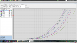
BTW I have no idea where the excessive 1/f noise of the entire amplifier comes from. The JFET contribution seems OK, LTspice shows no other component but the damping resistor that has any influence worth talking of.
It's just that the sum is much more than the parts.
BTW2: Is there a way to fix the y-axis of the plots at a range that I want permanently? Every new simulation forces me to set up it again.
\Gerhard
Attachments
Last edited:
I can't for the life of me find my 1A7A manual right now.
1A7 manual can be had here: http://bama.edebris.com/manuals/tek/1a7
The 1A7A here: TEKTRONIX 1A7A PLUGIN SM Service Manual download, schematics, eeprom, repair info for electronics experts
The 1A7 does have resistors in parallel with inductors and paralleled tubes. The 1A7A has only resistors.
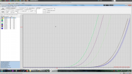
BTW I have no idea where the excessive 1/f noise of the entire amplifier comes from. The JFET contribution seems OK, LTspice shows no other component but the damping resistor that has any influence worth talking of.
Does LTSPICE have a way to log all the noise contributors vs. f? It certainly has to compute them. We had a command to print out all the noise contributors in order at a given f with a syntax to push into the models/subcircuits if need be.
BTW I have no idea where the excessive 1/f noise of the entire amplifier comes from. The JFET contribution seems OK, LTspice shows no other component but the damping resistor that has any influence worth talking of.
Spice barely models the GR noise, usually the most common source of LF noise beyond the ubiquitous 1/f noise.
Pure 1/f noise has a 10dB/decade slope, everything above that is usually GR noise.
Last edited:
- LMH6702 won't drive a 20ohm load, it has only 80mA output current.The ugly thing about the beads is that at low frequencies they are just a high-Q inductor and at high frequencies they do not short the damping resistor anymore. And their intended losses produce noise also, they can be modeled as a series resistance.
BTW I have no idea where the excessive 1/f noise of the entire amplifier comes from. The JFET contribution seems OK, LTspice shows no other component but the damping resistor that has any influence worth talking of.
It's just that the sum is much more than the parts.
- Why do you need a servo if you have C1 DC block? The servo would only mess the input stage, the DC loop is broken.
Spice barely models the GR noise, usually the most common source of LF noise beyond the ubiquitous 1/f noise.
I assumed we were talking about the simulation results.
- Home
- Design & Build
- Equipment & Tools
- My version of the G = 1000 low noise measurement amp (for Ikoflexer)