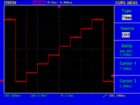
Not pretty but should do.
An externally hosted image should be here but it was not working when we last tested it.
Early in this thread the question was of how to sample plate current without a differential probe was raised. A differential input amp was shown, but it looked like that had a very limited input voltage range, limiting use the the ground leg of the plate supply or the cathode (which would need the grid currents subtracted to be accurate. One alternate method that would provide isolation is the hall effect sensor. It functons like a (powered) current transformer having DC response. Another is to use a linearized opto-coupler. In a unit with an LED and TWO photodiodes, using the second diode in the feedback loop of an amp driving the LED, the transfer function to the second (isolated output) photodiode becomes linearized. Doing that is described in Vishay Semiconductor app note 50, Designing Linear Amplifiers Using the IL300 Optocoupler. http://instruct1.cit.cornell.edu/courses/ece5030/labs/f2009/appn50vishay.pdf
Early in this thread the question was of how to sample plate current without a differential probe was raised. A differential input amp was shown, but it looked like that had a very limited input voltage range, limiting use the the ground leg of the plate supply or the cathode (which would need the grid currents subtracted to be accurate. One alternate method that would provide isolation is the hall effect sensor. It functons like a (powered) current transformer having DC response. Another is to use a linearized opto-coupler. In a unit with an LED and TWO photodiodes, using the second diode in the feedback loop of an amp driving the LED, the transfer function to the second (isolated output) photodiode becomes linearized. Doing that is described in Vishay Semiconductor app note 50, Designing Linear Amplifiers Using the IL300 Optocoupler. http://instruct1.cit.cornell.edu/courses/ece5030/labs/f2009/appn50vishay.pdf
Very interesting way of isolating the measurement of the anode current. With two op amps and the IL300 you can get the job done. Have you tried this?
Cheers, ale
Not pretty but should do.

Thanks
Which frequency are u using on your grid signal?
Are you still driving anode with mains rectified and not filtered?
Cheers
Ale
Hi Alfredo,
Thanks. So I could simple drop in your 4046/4017 stage before my 4520 counter as I'm using a similar clock circuit (instead of a 555 as ST I'm using a LM311 comparator) and with a mains frequency of 50Hz (UK) I could get a clock frequency of 200Hz. Do you think it will be enough to improve the screen refresh?
Thanks,
Ale
Very interesting way of isolating the measurement of the anode current. With two op amps and the IL300 you can get the job done. Have you tried this?
Cheers, ale
No, there are not any feedback enhanced optos in test equipment here yet. To avoid extra floating power supplies and circuitry at high voltage, I'm leaning more towards use of Hall effect current sensing. I was looking at the opto-isolators for a feedback path in another application, but concluded that besides bringing more complexity than I wanted, they were too marginal in terms of bandwidth, linearity, and signal to noise ratio to be part my quest to rid the world of evil screen-induced kinkiness distortions in pentode-connected amps.
Last edited:
Hi Alfredo,
Thanks. So I could simple drop in your 4046/4017 stage before my 4520 counter as I'm using a similar clock circuit (instead of a 555 as ST I'm using a LM311 comparator) and with a mains frequency of 50Hz (UK) I could get a clock frequency of 200Hz. Do you think it will be enough to improve the screen refresh?
Thanks,
Ale
Yes, right before the 4520. It should improve as the complete step family will take half the time. Also, controlling the number of steps per family helps. I currently do this with a comparator that resets the counter. You need to use a precision pot to have good control (to go one step at a time)
I can see it now, homes of the future with 400 Hz power generated from solar power. "Faster refresh for your curve tracers". Adding a little positive feedback to a comparator turns it into a Schmidt trigger which could prevent erratic behavior if there's some noise on the power line sample used for the frequency reference. Sometimes it is more convenient to use the 40106B, 74C13, or 7413.
Doing that is described in Vishay Semiconductor app note 50, Designing Linear Amplifiers Using the IL300 Optocoupler. http://instruct1.cit.cornell.edu/courses/ece5030/labs/f2009/appn50vishay.pdf
IL300 is a bit faster than the HCNR200 -- I know as I bought a tube of them from a guy about 6 years ago. I think that there's a SPICE model for the HCNR200 floating around -- used to be on HP's website before they spun off Agilent, which was before they spun off Avago.
Last edited:
I can see it now, homes of the future with 400 Hz power generated from solar power. "Faster refresh for your curve tracers". Adding a little positive feedback to a comparator turns it into a Schmidt trigger which could prevent erratic behavior if there's some noise on the power line sample used for the frequency reference. Sometimes it is more convenient to use the 40106B, 74C13, or 7413.
Thanks. Will add an Rf to the LM311.
")
Not pretty but should do.
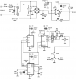
Hi Alfredo, is not clear in the picture. Can you please confirm the values of your PLL?
Resistor between pins 13 and 9 is 4M7?
Resistor between pin 11 and ground is 4.6K?
Many thanks
Ale
IL300 is a bit faster than the HCNR200 -- I know as I bought a tube of them from a guy about 6 years ago. I think that there's a SPICE model for the HCNR200 floating around -- used to be on HP's website before they spun off Agilent, which was before they spun off Avago.
So many things to get samples of and try. I just ran across some information on Hall effect devices I will check out. I'm not sure how well they work at low currents, but they look easy to use. Allegro MicroSystems - 0 to 50 A Integrated Conductor Sensor ICs
Hi Alfredo, it's just the clock board which I managed to build. Need to etch the anode and grid driver board,hopefully over the weekend if I get time.
Just realised that since I'm driving the LM311 with 100Hz and replicating your PLL taking the divider output from 4 I ended up with 2.5ms (400Hz) steps. I should reduce divider to get 200Hz otherwise with a 100Hz anode signal won't work properly?
Thanks
Ale
Just realised that since I'm driving the LM311 with 100Hz and replicating your PLL taking the divider output from 4 I ended up with 2.5ms (400Hz) steps. I should reduce divider to get 200Hz otherwise with a 100Hz anode signal won't work properly?
Thanks
Ale
- Status
- This old topic is closed. If you want to reopen this topic, contact a moderator using the "Report Post" button.
- Home
- Design & Build
- Equipment & Tools
- DIY Curve Tracer