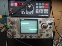
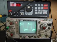
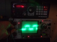
I'm new to using a scope as diagnostic tool and would like to check my steps/ get some guidance. These shots are taken across the secondary of a preamp (10Y) line output transformer connected to the input of a 4 pole LC line level crossover with rated impedance of 5K Ohm. Am I right in thinking that the ringing from 2.5KHz. and up is caused by interaction of the inductors?
The 20Khz. Square is completely beyond me . . . . Can anybody help with some comments? Thanks.
The 20Khz. Square is completely beyond me . . . . Can anybody help with some comments? Thanks.
Attachments
Here are a few basics for square wave testing, which is actually a form of pulse testing.
For best waveform quaility the output of your source generator should be terminated with it's characteristic output impedance. This is done at the far end of the coax cable where it meets the DUT. (device under test) An unterminated line will allow overshoot.
When testing a preamp (or any amp) it's output should be terminated in it's characteristic impedance with a non-inductive load resistor and nothing else. If unsure of the required output impedance, choose a typical working impedance that is reasonable. External L's and C's will grossly affect the waveform giving false indications of it's performance.
Now, the severe tilt at 100Hz is because your scope is rolling it off. Set the scope input to DC coupling. The drooping will flatten out.
Because a square wave is composed of many higher harmonics, for testing and analyzing purposes, they will equate upward by a factor of ten over the fundamental. This means that a frequency of 2500 to 3000Hz is the highest one should use when transformers are in the signal path. These will equate out to 25K and 30KHz respectively. Two frequencies are usually enough for a full range test. One low and one high. Remember for frequencies F÷10 (low) and Fx10 (high).
Some people will say to go ahead and use a 10KHz square wave just to see how good things really are. (or aren't) But you will be asking the transformer to pass 100KHz worth of harmonics which they won't do in most cases. So the rolled off and distorted leading corner will be of little meaning.
Circuit dampening is indicated by the shape at the top rising edge of the square wave. A well dampened circuit is shown by a waveform without overshoot. Poor dampening results in a train of oscillations after the inital rise. Waveforms with unequal positive and negative amplitudes indicates non-linear distortion. A rounded leading corner indicates poor HF response, while a downward tilting top and bottom means poor LF response.
Square wave testing should be done at a level well under the overload point of the DUT. An overloaded amp will make a square wave look better then it actually may be.
Last edited:
Nice tutorial!
I would suggests that this is still worth trying. A rolled-off leading edge suggests a better stability margin, and is more desirable than a leading edge which shows an overshoot or ringing.Some people will say to go ahead and use a 10KHz square wave just to see how good things really are. (or aren't) But you will be asking the transformer to pass 100KHz worth of harmonics which they won't do in most cases. So the rolled off and distorted leading corner will be of little meaning.
Thanks very much for your posts. It was very helpful. HollowState, you gave me everything I needed to get at it, many thanks.
I checked the Ramsey generator again and its output is very clean throughout its range. I also checked again using a 70Ohm resistor across its connection to the preamp but there was almost no change that I could see.
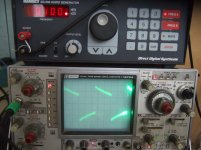
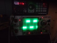
What made me feel it was time to stop doing everything by ear and start using test gear was the nasty little edge that was sort of tearing at the ear or making the scalp crawl. Last night I put the scope on the grid with the preamp turned off and got the first shot below. Wondering how rf was getting going so well with no power, tonight I changed the value of the grid stop resister and added a bead to it. I also put beads on the filament supply leads at the socket. This had a huge effect on sound though when I scoped it it looked almost the same. Then while noodling around on the scope controls I noticed that as I was switching from AC input to DC through the GND setting at center the trace briefly went clean. I then found it is possible to hold the switch at a point between the coupling and ground and then see a very clean trace. I'm not sure whether this means the scope has a problem or if holding the switch at a some midpoint is somehow filtering rf. My guess is that the scope is feeling its age and needs cleaning or servicing.
The big thing for me is both that I got started with the Oscilloscope and also that having put a couple of beads and a higher value grid stopper the sound is so utterly different that even my girlfriend stood there with her mouth open in surprise at the huge difference an apparently small change can make. It seems as if there is more gain as well, making me wonder if inaudible hf oscillation can lower the tube's gain. . . .
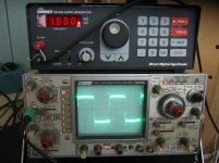
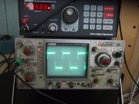
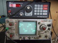
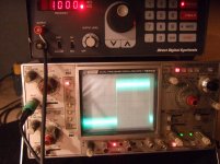
Pic 1 ) Signal at grid with preamp turned off. 2) Signal at output after bead and grid stopper added. 3) Same but with switch held in intermediate position.
If I get time tomorrow I'll do another full test of the preamp.
Thanks again ! ! !
I checked the Ramsey generator again and its output is very clean throughout its range. I also checked again using a 70Ohm resistor across its connection to the preamp but there was almost no change that I could see.
What made me feel it was time to stop doing everything by ear and start using test gear was the nasty little edge that was sort of tearing at the ear or making the scalp crawl. Last night I put the scope on the grid with the preamp turned off and got the first shot below. Wondering how rf was getting going so well with no power, tonight I changed the value of the grid stop resister and added a bead to it. I also put beads on the filament supply leads at the socket. This had a huge effect on sound though when I scoped it it looked almost the same. Then while noodling around on the scope controls I noticed that as I was switching from AC input to DC through the GND setting at center the trace briefly went clean. I then found it is possible to hold the switch at a point between the coupling and ground and then see a very clean trace. I'm not sure whether this means the scope has a problem or if holding the switch at a some midpoint is somehow filtering rf. My guess is that the scope is feeling its age and needs cleaning or servicing.
The big thing for me is both that I got started with the Oscilloscope and also that having put a couple of beads and a higher value grid stopper the sound is so utterly different that even my girlfriend stood there with her mouth open in surprise at the huge difference an apparently small change can make. It seems as if there is more gain as well, making me wonder if inaudible hf oscillation can lower the tube's gain. . . .
Pic 1 ) Signal at grid with preamp turned off. 2) Signal at output after bead and grid stopper added. 3) Same but with switch held in intermediate position.
If I get time tomorrow I'll do another full test of the preamp.
Thanks again ! ! !
Attachments
- Status
- This old topic is closed. If you want to reopen this topic, contact a moderator using the "Report Post" button.