Hi all,
I started the adventure to build Bob's THD Analyzer.
I made new PCB for my implementation.
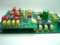
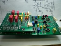
They are: one for Sine Generator and Output Attenuator with the connector for the switch capacitors range board.
The cap sw PCB for Sine Gen, and Filter range (two equal for both).
One for Filter, Amp and Freq Detect.
One for Output Filter with connector for the Meter
One (little) for Meter circuits. Mount AD536AH for RMS conversion
One for Input Attenuator/Amplifier
I still have not decided how to switch the resistance of the frequency, probably Optofet or Photoresistors but they latter have serious problems of thermal drift.
....le first photos
I started the adventure to build Bob's THD Analyzer.
I made new PCB for my implementation.
They are: one for Sine Generator and Output Attenuator with the connector for the switch capacitors range board.
The cap sw PCB for Sine Gen, and Filter range (two equal for both).
One for Filter, Amp and Freq Detect.
One for Output Filter with connector for the Meter
One (little) for Meter circuits. Mount AD536AH for RMS conversion
One for Input Attenuator/Amplifier
I still have not decided how to switch the resistance of the frequency, probably Optofet or Photoresistors but they latter have serious problems of thermal drift.
....le first photos
Attachments
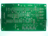
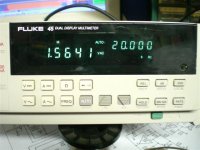
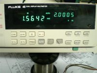
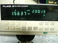
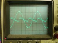
These output levels at various frequencies.
(The 200KHZ is the same level )
Note that with the 200pF Wima (in the photos) the generator was unable to go beyond 70kHz. Now I replaced them with Silver Mica and it reaches up to 250kHz without problems and with the same output level!
Test of distortion was done with Hameg HM8027 but it reveals nothing! (Long life to Bob).
...to be continued
Giuliano
Attachments
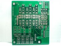
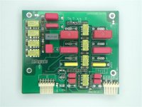
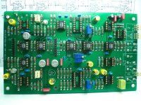
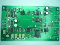
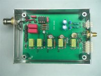
This is the, tested, Voltage-controlled bandpass filter with on-board caps-switch pcb.
The empty sockets of the IC refers to the amplitude and frequency detector and LED tuning frequency, in progress.
To be continued.
Hello
The empty sockets of the IC refers to the amplitude and frequency detector and LED tuning frequency, in progress.
To be continued.
Hello
Attachments
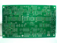
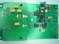
The circuit does not oscillate in the range of 200 kHz if resistors (E) - (F) connections are longer than 2 / 3 inches. It is even worse if I use shielded cable.
If increase the value of C (LN) only (470pF i.e.), then the circuit takes to oscillate (frequency appropriate to the capacity added) and by bypass cap resistors series.
I do not think the PCB tracks are longer than the original circuit wiring.
Which is the reason for that?
Resistors (F)-(E) values are 10 binary connecting so as to obtain intermediate frequency values.
1024 steps provide hertz fractions for low ranges and up to 175 Hz in the highest range.
Attachments
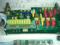
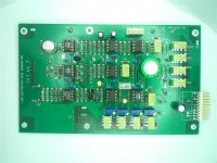
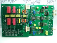
The input control level box.
After several attempts, I opted for trimmer capacitor to obtain constant amplitude on the entire range.
To next...
Nice work!!
I'm sorry I did not catch this thread earlier.
Best regards,
Bob
Thanks Bob,
the compliment said by you is worth more.
I take this opportunity to know the reason about this?
Quote:
The circuit does not oscillate in the range of 200 kHz if resistors (E) - (F) connections are Longer Than 2 / 3 inches. It Is Worse even if I use shielded cable.
If Increase the value of C (LN) only (ie 470pF), then the circuit Takes to swing (frequency appropriate to the capacity added) by and bypass cap series resistors.
I do not think the PCB tracks are Longer Than The original circuit wiring.
Which is the reason for that?
Thanks in advance
Giuliano
")
Good idea.
I think there are a few areas which can improve with an update.
The least is balanced input / output from analyzer and oscillator.
Here you can find my humble attempt at that :
http://www.diyaudio.com/forums/solid-state/154260-my-implementation-cordell-distortion-analyser.html
Also Glen has done a lot of work on Bob's design. See :
An Audio T.H.D. Analyser
Patrick
Hi everyone,
I see that this project will never fade!
For various reasons, job, family etc ... I have not yet completed it.
Guilty even of too many options that I decided to add: Frequency counter and two RMS digital voltmeter (for IN and OUT signal).
I am happy to share the PCBs files with you.
But PCBs are Circad format. If it is not 'a problem for you.
If necessary, I have the standard Gerber files.
If someone wishes, I have available a complete set of PCBs.
They are designed for use with 9V mini relay (AGN20009) instead switches.
Gift a few 2N4091, for those who buy the PCB.
As soon as possible, if you wish, I provide the link with all files.
Have a nice day
Giuliano
Hi,
this the Gerber Cordell THD files link.
https://www.dropbox.com/sh/ix4balwfq3vurzo/iTlXkNm5l7
I am available for any information
BR
giuliano
this the Gerber Cordell THD files link.
https://www.dropbox.com/sh/ix4balwfq3vurzo/iTlXkNm5l7
I am available for any information
BR
giuliano
- Status
- This old topic is closed. If you want to reopen this topic, contact a moderator using the "Report Post" button.
- Home
- Design & Build
- Equipment & Tools
- Another realization of Bob Cordell's THD Analyzer