Okay, that's great! It never pays to have any doubts on your test instrument readings. It is not foolish to test the battery, that's step #1 in calibration. We actually threw out the batteries and installed new alkaline batteries. Can you measure the battery voltage inside the case where the battery clips solder on? That will ensure that there is full continuity right into the circuit. Something doesn't look right with your beta measurements.
The scales on the IT-18 are X1 and X10. Read the scale directly on the X1 scale and multiply the meter indication by a factor of 10 on the X10 scale. I normally start on the X10 scale because most transistors have beta higher than 20. So, set the beta cal so the pointer sits over the furthest right hand lines on the meter scales. Don't touch that again for the short time you are using it at one sitting. These meters do not have the best balance, so set the cal with the meter level and do all your testing in the same position. Also, try to keep the transistor you are testing at room temperature. Don't hold it in your hand or fingers.
Hmm, that is how I thought the scale switch should work, so my confusion comes from the fact that it's apparently not working correctly. If it were working correctly, a reading of 70 when set to X1 should read 7 when set to X10, right? That's not what's happening now.
It does seem to calibrate correctly using the resistor and following the directions (following directions is the one thing I can do competently!), so I'm wondering if maybe one or more switches is giving intermittent contact. I measured voltage on the battery on the leads soldered to the case, so the battery is making good contact and supplying the correct voltage to the circuit.
Is the gain reading on my DVM accurate enough to use for matching?
Last edited:
Hi Fred,
You're ahead of me then. The fact that you measured your battery voltage in the circuit, rather than at the battery terminals really shows me that you like to confirm the results you are looking for. An excellent trait, one I have seen in few technicians. There's an "atta-boy" for you.") No kidding, I am impressed.
No kidding, I am impressed.
Now that you are making me think about how these meters actually work, I had to actually check the switch using a transistor. The fact is, it's been over 25 years since I have even thought about how this thing is supposed to work - to put it into words. It's something I use subconsciously without even thinking about. So, if you are on the X10 scale and read a beta of ~9 (X10=90), throwing the switch to X1 should cause the pointer to move downscale to where you would imagine a reading of 90 would be. Reading a beta over 100 is really a very rough guess, and a reasonable setup since most transistors tended to have beta readings of 100 or less. Our newer signal transistors were not something they figured you would need an accurate answer on anyway. That's because temperature plays such a big role in these readings. For the same reason, your DVM reading is only a very approximate thing, the danger here is that it gives you actual numbers. That fools you into thinking you have more accuracy that you actually do.
For matching power transistors, use the IT-18 while being careful not to handle the transistors. Room temperature is the best you can do. Once things start heating up, any hope of a match is greatly reduced. If you are matching signal transistors, you pretty much have to use the jig I mentioned. At least both transistors are at a similar and are running the same current if a match is indicated. I do use an IT-121 for more accurate or detailed measurements (or to test J-Fets), but it takes too long to use in bench work. I actually got that as an unbuilt kit about 8 years ago from my father. It was fantastic to be able to build a Heathkit after so long. I think we have missed out on a lot since Heathkit stopped selling kits.
When running a service shop, I tried to get the guys to use things like the IT-18 for the simple reason that it re-enforced that the readings were approximate. One thing you will find is that if you have a couple transistors that measure very close in gain, the pair that have the same cal point on the meter will match pretty closely. Earlier, I think I told you to leave the calibration control the same for all measurements, that was wrong - sorry. I was doing something else (for which this was true) and advised you incorrectly. You calibrate for each transistor. If you warm the part up, or cool it, the calibration point will drift. If you have just de-soldered a transistor, you have to let it cool before trying to take an accurate reading. But keep in mind that for general circuit operation, having a gain that is "in the correct range" for that type, with no leakage, is what you are looking for. Abnormal high or low readings are cause for concern. I retest those and call them bad if they test the same.
I hope that helps Fred, Chris
You're ahead of me then. The fact that you measured your battery voltage in the circuit, rather than at the battery terminals really shows me that you like to confirm the results you are looking for. An excellent trait, one I have seen in few technicians. There's an "atta-boy" for you.
No kidding, I am impressed.Now that you are making me think about how these meters actually work, I had to actually check the switch using a transistor. The fact is, it's been over 25 years since I have even thought about how this thing is supposed to work - to put it into words. It's something I use subconsciously without even thinking about. So, if you are on the X10 scale and read a beta of ~9 (X10=90), throwing the switch to X1 should cause the pointer to move downscale to where you would imagine a reading of 90 would be. Reading a beta over 100 is really a very rough guess, and a reasonable setup since most transistors tended to have beta readings of 100 or less. Our newer signal transistors were not something they figured you would need an accurate answer on anyway. That's because temperature plays such a big role in these readings. For the same reason, your DVM reading is only a very approximate thing, the danger here is that it gives you actual numbers. That fools you into thinking you have more accuracy that you actually do.
For matching power transistors, use the IT-18 while being careful not to handle the transistors. Room temperature is the best you can do. Once things start heating up, any hope of a match is greatly reduced. If you are matching signal transistors, you pretty much have to use the jig I mentioned. At least both transistors are at a similar and are running the same current if a match is indicated. I do use an IT-121 for more accurate or detailed measurements (or to test J-Fets), but it takes too long to use in bench work. I actually got that as an unbuilt kit about 8 years ago from my father. It was fantastic to be able to build a Heathkit after so long. I think we have missed out on a lot since Heathkit stopped selling kits.
When running a service shop, I tried to get the guys to use things like the IT-18 for the simple reason that it re-enforced that the readings were approximate. One thing you will find is that if you have a couple transistors that measure very close in gain, the pair that have the same cal point on the meter will match pretty closely. Earlier, I think I told you to leave the calibration control the same for all measurements, that was wrong - sorry. I was doing something else (for which this was true) and advised you incorrectly. You calibrate for each transistor. If you warm the part up, or cool it, the calibration point will drift. If you have just de-soldered a transistor, you have to let it cool before trying to take an accurate reading. But keep in mind that for general circuit operation, having a gain that is "in the correct range" for that type, with no leakage, is what you are looking for. Abnormal high or low readings are cause for concern. I retest those and call them bad if they test the same.
I hope that helps Fred, Chris
Okay, so if I understand you correctly, I was wrong before. My DVM and the IT-18 ARE using the same scale. So I can use the DVM as a "reality check" against the IT-18, right?
Doing that with a 2SC2912, I get 264 stable on the DVM, but 30 on the IT-18 (X1 scale) or over 100 (X10). It does calibrate normally, meaning I can hook up the transistor and use the beta-cal control to move the needle to the CAL mark.
One thing odd about this IT-18 (an ebay purchase) is that instead of the little 10 kohm leakage adjust pot on the back of the function switch, the builder wired up a 10 kohm shafted pot on leads. I assume they did this in order to the calibration procedure without having to pull the chassis out of the box. I don't see how this would make any difference electronically, but I don't know much.
Anyway, I don't think this IT-18 is working right, at least not the beta testing amp. The leakage tests appear to work, but I don't have any way of proving that (other than shorting the lead).
All this transistor testing chat should be in a different thread. Chris, can you move it as a moderator?
Hi Fred,
Your wish is my command ... posts split and moved.
If you are getting numbers that are close between them, yes. Each will provide a sanity check for the other. A "cross check" in lab speak. The fact that you can calibrate normally is a very good sign.
While I'm thinking of it, watch out for pencil marks or fluid residue marks. These can be conductive
You can test leakage with your finger or a high value resistor. Shorting the leads is hard on the meter.
Once you have it running, it will last you years. After all, I'm still using the one I bought as a kid, and it's been in the hands of idiots at my shop. I was dropped twice, breaking the meter cover twice. It's glued together and looks like heck - but it works fine.
-Chris
Your wish is my command ... posts split and moved.
If you are getting numbers that are close between them, yes. Each will provide a sanity check for the other. A "cross check" in lab speak. The fact that you can calibrate normally is a very good sign.
Oh darn! I hate it when people get creative for no good reason. There is no good reason to make this control accessible at all. Set and forget is what this thing is all about. I was thinking, "how can you mess up a simple meter?" Looks like someone found a way all right!the builder wired up a 10 kohm shafted pot on leads.
One should never deviate from a working plan without a very good reason. In this case, the pot may have the wrong taper, the leads may cause trouble due to inductance or noise pickup. My advice would be to locate a control that can be mounted as close to the stock position as possible. Once you have the control, carefully check all the wiring and install the new control in the correct location. Then, run through the calibration procedure, it's easy as you know. It might be worthwhile to use a solder sucker to remove the bulk of the solder off the connections. Look for tarnish or black deposits. Remove any you find, then apply fresh solder. Not too much, just do it like the manual shows. This will eliminate any bad solder connections. Do not just add solder, that will not help you at all. In fact, you could end up with solder stuck inside components or shorting. When you use a solder sucker, it removes most of the heat energy with the molten solder. Then you can inspect the surfaces of the conductors and re-solder everything properly.I don't see how this would make any difference electronically, but I don't know much.
While I'm thinking of it, watch out for pencil marks or fluid residue marks. These can be conductive
You can test leakage with your finger or a high value resistor. Shorting the leads is hard on the meter.
Once you have it running, it will last you years. After all, I'm still using the one I bought as a kid, and it's been in the hands of idiots at my shop. I was dropped twice, breaking the meter cover twice. It's glued together and looks like heck - but it works fine.
-Chris
Well, I guess the ideal thing to do would be to rebuild it from the beginning. Then I can be positive it's wired correctly and I can test the values of the resistors and cap.
But I'll start by checking the switches for proper continuity and checking their wiring to see if it's correct.
Can you tell me more specifically how you would test the leakage functions with your finger? Do you mean using it as a resistor of sorts?
I can tell it's worth putting some time and effort into this thing, I just wish I had more of both of those to spare
My advice would be to locate a control that can be mounted as close to the stock position as possible.
How about this: M64Y103KB40 Vishay/Spectrol Trimmer Resistors - Multi Turn
I might have to use a quarter-inch or so fly-out to extend the leads to the width of the holes/lugs on the rotary switch. I could use shielded but it's hard to imagine the circuit is that sensitive to inductance. (Not to mention that would be some dang fiddly soldering.)
So the wiring appears to be correct (matches the manual). I checked all the resistors and they are the correct values. I checked the x10 switch for continuity and it is working correctly. I cleaned everything again with deoxit contact cleaner.
But still, I don't think the gain measuring circuit is working correctly. I can do the "new battery" calibration correctly. And, I can adjust bias cal correctly (slowly moving the needle to the cal point when a transistor is connected), but pushing the test switch always deflects the needle to around 60, no matter the transistor. In other words, a transistor that reads 200 hfe on my DVM still reads around 60 on the IT-18. The reading does not change significantly, or logically when flipping to the x10 range. In other words, the needle only deflects a little, if at all, so that 60 becomes 500 (50x10).
I didn't test the capacitor yet, and I'm still using the shafted pot. But I don't see how those would cause the behavior I'm seeing, given that I can calibrate normally using the resistor procedure, and that biasCAL works when a transistor is connected.
In other words, stumped again.
Last edited:
Hi Pete,
Takes all kinds of people I guess! Not too proud of his workmanship either. The fault was never corrected.
Hi Fred,
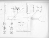
I have a picture of how mine looks. It was factory wired (it was the only one they had - I wanted the kit). May have been built at the store, I can't say for sure. I was told it was new, and it appeared to be. I've included some scans of the manual, I hope they can help other members who are looking in, trying to help. I think you have the manual, right?
When you set the meter pointer on the "Cal" mark in preparation to measure beta, you are actually setting the emitter current to 1 mA - almost exactly. This information can be useful, and you can verify the current by putting the emitter lead in series with your multimeter (switched to current mode) and read the value. That will provide a great test to see how close you are to the way it should be working. There is also the cal procedure using a 180 ohm resistor. I bought a 1% resistor (actually a bunch, and selected the most accurate one) and fixed it inside. That allows me to have a good idea if anything is changing with the meter. This brings up an important point. This meter is sensitive to the voltage across the battery. Since I use it a lot, I've been thinking of building a power supply for it. This meter does not go through batteries, but I'd like to eliminate the variable created by an aging battery.
This meter is about the best there is for service bench use. It tells you exactly what you need to know, and does it quickly. There are more accurate meters out there, and Heathkit made some of those too. But they take more time to actually take a reading. This darn meter is pretty simple, and yet manages to be very accurate when compared to testing the transistor in a circuit where you can measure the actual currents and calculate the beta. If there is one meter I wish was available new, this is it.
I did buy a Heathkit IT-30 (?) [See below] transistor checker, but it went missing in the mail and I never did get it. It had a circular dial scale on the front panel and I wanted to restore it and see how close it was. Does anyone have one of these they don't want? I'll admit here and now that I have a weakness for test equipment, and I seem to have collected a number of Heathkit stuff.
I checked on Google, the transistor tester I didn't get was an IM-30. Here is a link that shows what it looks like. It seems to be more complicated to set up for service use than the IT-18. I really can't think of a better meter to use.
Why do I think so much of the Heathkit IT-18? Well, aside from being quick to use, it provides very close readings for beta. It also reminds the user that the reading is approximate due to the analog scale. A digital reading is useless and implies accuracy that does not exist. Also, this meter will read collector - base leakage current, and collector - emitter leakage current. except for shorted transistors that I find with my DVM, the leakage tests catch more failure modes than any other test I can think of. There are a small percentage that the beta test catches as well. Any transistor that has abnormally high or low beta for the type is condemned in my world.
I highly recommend this meter for bench use.
-Chris
Takes all kinds of people I guess! Not too proud of his workmanship either. The fault was never corrected.
Hi Fred,
I have a picture of how mine looks. It was factory wired (it was the only one they had - I wanted the kit). May have been built at the store, I can't say for sure. I was told it was new, and it appeared to be. I've included some scans of the manual, I hope they can help other members who are looking in, trying to help. I think you have the manual, right?
When you set the meter pointer on the "Cal" mark in preparation to measure beta, you are actually setting the emitter current to 1 mA - almost exactly. This information can be useful, and you can verify the current by putting the emitter lead in series with your multimeter (switched to current mode) and read the value. That will provide a great test to see how close you are to the way it should be working. There is also the cal procedure using a 180 ohm resistor. I bought a 1% resistor (actually a bunch, and selected the most accurate one) and fixed it inside. That allows me to have a good idea if anything is changing with the meter. This brings up an important point. This meter is sensitive to the voltage across the battery. Since I use it a lot, I've been thinking of building a power supply for it. This meter does not go through batteries, but I'd like to eliminate the variable created by an aging battery.
This meter is about the best there is for service bench use. It tells you exactly what you need to know, and does it quickly. There are more accurate meters out there, and Heathkit made some of those too. But they take more time to actually take a reading. This darn meter is pretty simple, and yet manages to be very accurate when compared to testing the transistor in a circuit where you can measure the actual currents and calculate the beta. If there is one meter I wish was available new, this is it.
I did buy a Heathkit IT-30 (?) [See below] transistor checker, but it went missing in the mail and I never did get it. It had a circular dial scale on the front panel and I wanted to restore it and see how close it was. Does anyone have one of these they don't want? I'll admit here and now that I have a weakness for test equipment, and I seem to have collected a number of Heathkit stuff.
I checked on Google, the transistor tester I didn't get was an IM-30. Here is a link that shows what it looks like. It seems to be more complicated to set up for service use than the IT-18. I really can't think of a better meter to use.
Why do I think so much of the Heathkit IT-18? Well, aside from being quick to use, it provides very close readings for beta. It also reminds the user that the reading is approximate due to the analog scale. A digital reading is useless and implies accuracy that does not exist. Also, this meter will read collector - base leakage current, and collector - emitter leakage current. except for shorted transistors that I find with my DVM, the leakage tests catch more failure modes than any other test I can think of. There are a small percentage that the beta test catches as well. Any transistor that has abnormally high or low beta for the type is condemned in my world.
I highly recommend this meter for bench use.
-Chris
Attachments
I bought one of these on ebay recently and the X1/X10 switch was put in upside down so that they were opposite to the labels.
Figured out what was wrong with mine. See if you can guess...
Yep, upside down and wired backwards. Now my IT-18 works fine, readings jibe with my DVM. Yay!
Figured out what was wrong with mine. See if you can guess...
Yep, upside down and wired backwards. Now my IT-18 works fine, readings jibe with my DVM. Yay!
Excellent! Seems that was a common mistake!
Chris, I sent you an email last night, but here is the best place to discuss all things IT-18.
Hmmm, so builders turned the x1/x10 switch backwards. I have a sneaking suspicion that mine was built the same way too!
I'll run some of the checks that you suggested. I've kept it on my desk next to my computer and my guess is that it won't be put on a shelf any time soon!
I do have a question about setting beta calibration. Does the meter jump like crazy during cal? Mine is sooo sensitive and I just nudge the dial ever so slightly to get it lined up to the right over 'CAL' on the meter.
Last edited:
Excellent! Seems that was a common mistake!
It must have been. I picked up a IT-112 Curve Tracer with a switch in backwards. I don't remember which one, that was a long time ago.
Hmmm, so builders turned the x1/x10 switch backwards. I have a sneaking suspicion that mine was built the same way too!
I'll run some of the checks that you suggested. I've kept it on my desk next to my computer and my guess is that it won't be put on a shelf any time soon!
I do have a question about setting beta calibration. Does the meter jump like crazy during cal? Mine is sooo sensitive and I just nudge the dial ever so slightly to get it lined up to the right over 'CAL' on the meter.
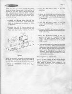
It's easy to tell if the switch is in backwards once you know what you're looking for. Compare it to the illustration in the manual and look for the two little marks that represent the two unused slots for solder tabs on the switch. The switch needs to be oriented as illustrated. You can see why people made the mistake!
My needle is quite sensitive when calibrating, just as you describe.
Good luck!
Hi sonidos,
Did I reply? I can't remember if I saw it or not. Please let me know as I've been told I have missed a few.
Setting the beta cal. is actually adjusting the transistor under test for a collector current of 1 mA. The adjustment is very touchy when testing lower gain transistors, try some high gain transistors like 2SC2240 or similar, even a real 2N3904 should be much easier to set up. The other possibility would be bad connections somewhere. Check the actual connections to the transistor, the leads for breaks and even the switch contacts inside your IT-18. Don't forget the calibration control.
It's best if you don't clean these parts unless they need it, otherwise you will wash out all the lubricants. Add oil to the shaft bearing. If the adjustment with a high gain part is smooth, you probably do not need to clean anything.
Hi Steve,
Was that an IT-121 you are talking about? They were pretty useful back then
-Chris
Thanks - got some work cut out for me
I definitely have some work cut out for me. I think the beta cal dial just was a bit gunky and seems to be working better now after playing with it a bit, but I got some numbers that I think are way off the mark.
I tested 8 each of Sanyo 2SD1047 and 2SB817 power transistors. I used the x1 scale and I was getting beta from as low as 6.8 to as high as 15. The NPNs ranged from 6.8 to 11. The PNPs ranged from 12 to 15. Selecting x10 didn't give me any useful results because it was measuring at about 1000 (100 x 10), and the beta for these trannies is supposed to be from 100 to 200 when measured at 1 A. Is it possible that 1 mA gives a different beta value on these boys?
Now I did try a Fairchild KSA992 (pnp type), which is a small signal type and x1 got a reading over 50, so I moved it to x10 and got a reading around 500, which is right in the middle of the published beta of 400 to 600. So that seems right and jibes with what you stated regarding measuring small signal trannies. I've got a few more other varieties and I'll give them a try tomorrow.
I did do some checking vs. the illustration and everything looks fine as far as wire layout, connections to switches, placement of resistors, the diode, and the ceramic cap. So I will probably check to see if maybe switch contacts need cleaning
Chris, no problem on the email. I set it about a day or two ago and it covers what I've added here on this thread. Much obliged to you guys. I hope to have this working right very soon. It's definitely a fun tool.
Last edited:
Hi sonidos,
My IT-18 measures those part numbers just fine. Interesting problem you have there. I have confirmed the readings with other transistor testers and also by setting up a test jig where I measured the values of collector and base currents directly. They agree within the error of the meter and other experimental effects. To be honest, even a change of temperature affects what you get for numbers.
The numbers at 1 mA correspond well with the numbers I get at higher currents. For sure there is going to be some difference, but the readings seem to be in the ball park.
Did you perform the calibration procedure on your meter? If not, start there. You can put a DVM in series with the emitter or collector of a high gain part and confirm your zero set point reads 1.0 mA. This is a very important point as the meter is based on this. Static on the plastic meter cover can throw your reading way off, as can a sticky movement (I hope your meter is okay!).
When cleaning a variable resistor, use only enough cleaner (not tuner cleaner !!!) to get things working and no more. There are lubricants inside that protect the carbon track. The problem area is the slip ring, not the carbon track! That's a popular misconception. I use a liquid cleaner with a hollow needle-like applicator and a rubber bulb for applying cleaning fluid. Sprays are a last resort as you get far too much in there, and it goes pretty much everywhere. Even the Caig pump applicator allows too much cleaner out.
The IT-18 will not measure a darlington properly due to the double VBE drops. Don't bother trying as it's a waste of time. Another battery in series with the base might work, but your gain reading will be in that compressed area at the top (bottom?) of the scale.
You can get matches using this meter, but it's difficult. That's why I put together a jig for that one purpose.
-Chris
My IT-18 measures those part numbers just fine. Interesting problem you have there. I have confirmed the readings with other transistor testers and also by setting up a test jig where I measured the values of collector and base currents directly. They agree within the error of the meter and other experimental effects. To be honest, even a change of temperature affects what you get for numbers.
The numbers at 1 mA correspond well with the numbers I get at higher currents. For sure there is going to be some difference, but the readings seem to be in the ball park.
Did you perform the calibration procedure on your meter? If not, start there. You can put a DVM in series with the emitter or collector of a high gain part and confirm your zero set point reads 1.0 mA. This is a very important point as the meter is based on this. Static on the plastic meter cover can throw your reading way off, as can a sticky movement (I hope your meter is okay!).
You don't want to ruin the control, it's a multi-turn control. Get some fine, single weight, light machine oil with zero additives and put some in the front of the bearing where the shaft enters the bushing. There will be some kind of a clip (leave it!), you want to get a bit of oil into the area behind the clip. Around to the rear, apply some of the same oil into the ball bearings and also into the rear of the sleeve bearing if you can. Work the control (it should be much looser) and clean up anything around the outside of the areas where you put the oil. You may need to do this a couple times, depending on how bad the control is. The same treatment is used for any rotating controls or switches. It is very important that you do not use 3n1, WD-40 or anything like those. Sewing machine oil is another to stay away from.I think the beta cal dial just was a bit gunky and seems to be working better now after playing with it a bit, but I got some numbers that I think are way off the mark.
When cleaning a variable resistor, use only enough cleaner (not tuner cleaner !!!) to get things working and no more. There are lubricants inside that protect the carbon track. The problem area is the slip ring, not the carbon track! That's a popular misconception. I use a liquid cleaner with a hollow needle-like applicator and a rubber bulb for applying cleaning fluid. Sprays are a last resort as you get far too much in there, and it goes pretty much everywhere. Even the Caig pump applicator allows too much cleaner out.
The IT-18 will not measure a darlington properly due to the double VBE drops. Don't bother trying as it's a waste of time. Another battery in series with the base might work, but your gain reading will be in that compressed area at the top (bottom?) of the scale.
You can get matches using this meter, but it's difficult. That's why I put together a jig for that one purpose.
-Chris
- Status
- This old topic is closed. If you want to reopen this topic, contact a moderator using the "Report Post" button.
- Home
- Design & Build
- Equipment & Tools
- Heathkit IT-18 transistor tester troubles