These days, really high speed DACs - not audio! - often use predistortion of the applied digital bit pattern to compensate for low level non-linearities in the device itself. Or, even for amplifier stages that might follow. At least in the case of the DAC chips, to a first approximation this is consistent from chip to chip.
So... Could this technique be applied here? Not only for any DAC but to any ADC. With a pc cranking out the data, there is far more than enough processing to do this.
Anybody here *really* good with Matlab and DSP algorithms?
So... Could this technique be applied here? Not only for any DAC but to any ADC. With a pc cranking out the data, there is far more than enough processing to do this.
Anybody here *really* good with Matlab and DSP algorithms?
At -120 dB errors I think any correction algorithm would need input from temperature ground plance currents etc and be frequency aware with the 10 decades of audio. I think the AKM ADC has some special stuff going on to do some corrections.
Personally I would use the CM6631 because the driver work on Windows (no licensing mess) and it works on OSX, Linux, and Android. I2S isolation is much harder than it first seems. USB isolation is not an option (the one that works is $400). An SPDIF isolation with transformers works real well. Clock locking schemes with sub 10 pS jitter are not difficult. Modularizing the project makes it much easier to see an end. In fact rather than dealing with making a USB interface I would just buy it off eBay if possible. That is a lot of thankless work otherwise.
Personally I would use the CM6631 because the driver work on Windows (no licensing mess) and it works on OSX, Linux, and Android. I2S isolation is much harder than it first seems. USB isolation is not an option (the one that works is $400). An SPDIF isolation with transformers works real well. Clock locking schemes with sub 10 pS jitter are not difficult. Modularizing the project makes it much easier to see an end. In fact rather than dealing with making a USB interface I would just buy it off eBay if possible. That is a lot of thankless work otherwise.
Well, yes. But, consider what you might be trying to attain.At -120 dB errors I think any correction algorithm would need input from temperature ground plance currents etc and be frequency aware with the 10 decades of audio. I think the AKM ADC has some special stuff going on to do some corrections.
At -120 dBc, you might be hoping to get maybe 10 or 20 dB of cancellation. In terms of feed forward type correction, that's not considered really hard. At least for the guys who do this sort of thing.
Often, the linearities are somewhat predictable, like asymmetrical rise and fall times for one of the modulators. That really helps.
Personally I would use the CM6631 because the driver work on Windows (no licensing mess) and it works on OSX, Linux, and Android. I2S isolation is much harder than it first seems. USB isolation is not an option (the one that works is $400). An SPDIF isolation with transformers works real well. Clock locking schemes with sub 10 pS jitter are not difficult. Modularizing the project makes it much easier to see an end. In fact rather than dealing with making a USB interface I would just buy it off eBay if possible. That is a lot of thankless work otherwise.
I2S isolation shouldn't be too bad with the NVE, AD, or SiLabs parts I would think? Especially for an ADC where you aren't too concerned about jitter on the I2S coming out. I guess you would have to isolate the USB shell from the chassis though and have separate transformer secondaries for the ADC side and the "USB/digital" side.
Master clock quality effects
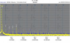
In the attached plot the blue trace is the AK5394A with its on board clock, a gate oscillator. The yellow trace is the exact same setup only with an external high performance 24.576 MHz clock. All of the artifacts are below -120 dB but clearly visible as artifacts above the noise floor.
In the attached plot the blue trace is the AK5394A with its on board clock, a gate oscillator. The yellow trace is the exact same setup only with an external high performance 24.576 MHz clock. All of the artifacts are below -120 dB but clearly visible as artifacts above the noise floor.
Attachments
Very interesting. I'm guessing that the clock still is passing through all the logic bits on the eval board as well.
I wonder how much better this device would work with MCLK (I think...) applied directly to the ADC and the other clocks derived in parallel. Perhaps some delay might be needed to synchronize all of it, but that should be possible. If it matters.
How you find the time to do all of this is a great mystery.
You can review the options on the AKD5394A demo board here: http://www.akm.com/akm/en/file/ev-board-manual/AK5394AVS.pdf I was using it in slave mode (default) at 192 KHz sample rate. If you are using multiple ADC's you will have no choice about using slave mode.
I apologize for not having any useful links immediately.
Mostly, I have dealt directly with the guys doing this work. I'm not sure how public the details are, but I'll try to find out. It's true that all of the work I'm familiar with is centered around much higher frequencies than audio, but I'm told the problems are very similar.
I'll see what I can find out.
I will still pursue asking the experts, but here is a paper that speaks in generalities about some approaches to digital predistortion techniques.
http://www.ece.rochester.edu/~sterling/icassp2007.pdf
There also is another approach, based on the idea that the test signal is pretty much deterministic, or could be made so.
Imagine that you take one of your high performance audio oscillators, and passively filter the harmonic output. In theory, harmonics will be buried well into the test system noise. So, if you apply that signal to your ADC system, ideally you should see nothing but the test tone. If you do, great. If there's other spurii in the results, these can be cancelled mathematically in the output. Are the tones gone? No, but they aren't part of the measurement. This is similar in concept to normalizing or calibrating amplitude response of a network analyzer. In that case you are not changing the nature if the applied signal, but instead are normalizing the results.
If this process is automated, it can be run at a host of levels and frequencies, giving an entire calibration table for the system. I think this is how the Agilent analyzers calibrate for X-parameter measurements.
That make sense? Why not use the computational capabilities of the control computer to help simplify measurements? The whole process could be used for both the generator side as well as the analyzer side. Done well, the generator could be pre-distorted to be essentially perfect, since you know what you want the output to look like - just add exactly the same level and exactly opposite in polarity tones to cancel the undesired products. Computational feed-forward, if you like.
Many of these ideas were already discussed, albeit in analog form, in the uber low distortion oscillator thread. I'm just suggesting getting the computer to do all the heavy lifting.
Last edited:
Hello Igor,
I only sale bare circuit board (or only with CPLD programmed), you must get others parts by yourself.
Of course, i also provide design files to build it without issue.
You need some skill to solder SMD parts, but nothing very difficult")
The AA5381 ADC has been designed to fit very well as measurement tool,
but you can of course use it as high-end audio recorder.
Regards.
Frex
I only sale bare circuit board (or only with CPLD programmed), you must get others parts by yourself.
Of course, i also provide design files to build it without issue.
You need some skill to solder SMD parts, but nothing very difficult
The AA5381 ADC has been designed to fit very well as measurement tool,
but you can of course use it as high-end audio recorder.
Regards.
Frex
Hi Frex!Hello Igor,
I only sale bare circuit board (or only with CPLD programmed), you must get others parts by yourself.
Of course, i also provide design files to build it without issue.
You need some skill to solder SMD parts, but nothing very difficult
The AA5381 ADC has been designed to fit very well as measurement tool,
but you can of course use it as high-end audio recorder.
Regards.
Frex
Well, may be should recollect my youth and get a huge soldering iron! Besides this will take time and order the the other the elements (unfortunately in my country, this may not be quite simple). If I do not find a suitable device for my purposes, I will turn to you. Although it would be great to get the finished product.
Hello Igor,
I understand. If you are really interested by finished one, and your not able to get parts,
i can sale you mine. So, i could build another one for me in my spare time...
Just send me a PM for that.
Regards.
Frex
Hello Frex!
And what about my question?
- Status
- This old topic is closed. If you want to reopen this topic, contact a moderator using the "Report Post" button.
- Home
- Design & Build
- Equipment & Tools
- DIY Analog-to-Digital Converter project.Audio measurements tool