PCB pictures
Hello,
PCBcart has made a very good job again...
Top quality pcb.
Now, just need to find the time to soldered all of that. I love that !
I will also post pictures when it will be soldered.
The pcb fit very well in it's housing !
Frex
Top and bottom view of the prototype pcb :
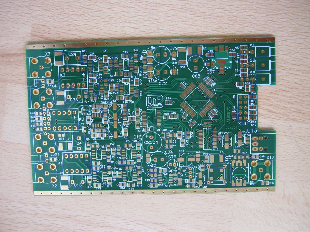
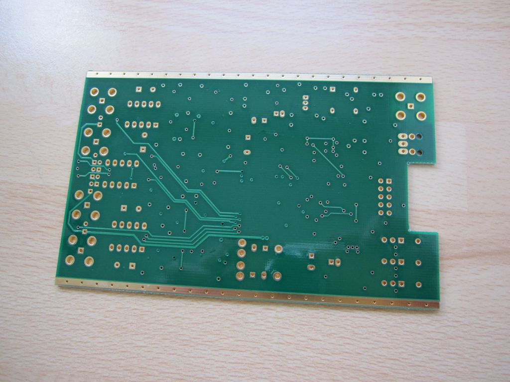
To follow...
Hello,
PCBcart has made a very good job again...
Top quality pcb.
Now, just need to find the time to soldered all of that. I love that !
I will also post pictures when it will be soldered.
The pcb fit very well in it's housing !
Frex
Top and bottom view of the prototype pcb :
To follow...
Mechanical check...
Hello,
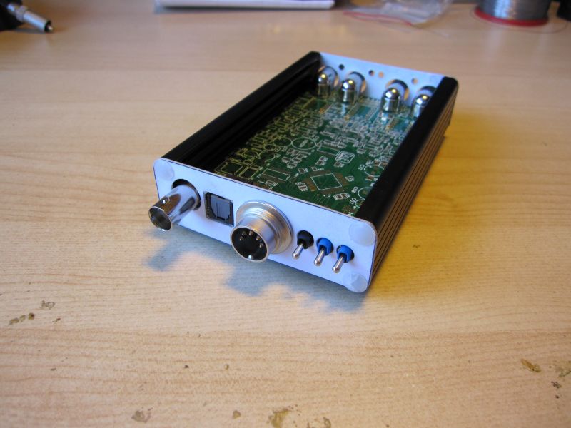
I have made a false front/rear panel in cardboard, for checking the positions of mechanical parts. All seem to be ok, i can drill the real panels.
For the SMD soldering, i must unfortunately wait until saturday or sunday to have enough time and tranquility.
and anothers pictures :
front view
top view
Frex.
Hello,
I have made a false front/rear panel in cardboard, for checking the positions of mechanical parts. All seem to be ok, i can drill the real panels.
For the SMD soldering, i must unfortunately wait until saturday or sunday to have enough time and tranquility.
and anothers pictures :
front view
top view
Frex.
Last edited:

Hello ikoflexer,
I'm happy that my job pleased you.
I use PCAD as EDA software (it is now part of Altium).
The price for me (including the PCB) is about 300€.
If i buy others pcbs, their price will be much less because tolling cost has been
already payed.
Also, some component are optional.
The clock can be a low cost SMD oscillator (~5€) or a ultra low jitter TenT-Lab XO (40€).
The SPDIF transformer can be a low cost Murata (3€) or the high-end high CMRR digital transformer SC947-02 from Scientific-Conversion.
These different choice can also change of course the final price.
FRex.
Perfect job, I wish I could handle these SMD's ...
As promised, some measurements of the PCM4222 eval. board for comparison.
Test chain:
Krohn Hite 4400A ( 50 Ohm output impedance, SLA battery driven ) ->
PCM 4222 eval. board ( 560 Ohm input impedance, unbalanced input, SLA battery driven ) ->
E-MU 1616m ( coax spdif input )
At 192k, I had to replace the E-MU PS with a linear one, cause it gives a 63kHz switching artefact.
Although I own a license of HpW works and Dr. Jordan Win Audio MLS, I decided to use the latest SpectraPLUS 5.0 demo, fully functional for 30 days.
http://www.spectraplus.com/Downloads/specplus_50_setup.exe
0dB means ADC full scale, board input 4V rms.
Next step will be to add an AD797 inverter to the Krohn, getting balanced out,
hopefully the AD797 will drive 560 Ohm at the "sweetspot" input level ( app. -26dB ) without adding distortion.
Attachments
AA5381, first powering...
Hello,
Thank you for those detailed measurements ghg.
I'm very surprised by the level of the noise floor at 192kHz!
Can you measure the RMS power level when input is shorted,
and at different sampling rate ?
(Spectraplus can display it)
I agree, it's a really interesting card, especially for this price.
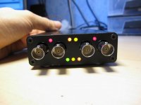
For my own ADC project, powering is ok and PLD is programmed and all work fine. The 3 rear switch allow to select sampling rate (48/96/192), AC or DC input coupling, single-ended or differential input, and offset calibration for 5s.
I have start today some short measurements with my lab PSU.
When all tests will be done, i will post measurements results and some pics of
the ADC working. May be a video...What do you think ?
Frex.
Hello,
Thank you for those detailed measurements ghg.
I'm very surprised by the level of the noise floor at 192kHz!
Can you measure the RMS power level when input is shorted,
and at different sampling rate ?
(Spectraplus can display it)
I agree, it's a really interesting card, especially for this price.
For my own ADC project, powering is ok and PLD is programmed and all work fine. The 3 rear switch allow to select sampling rate (48/96/192), AC or DC input coupling, single-ended or differential input, and offset calibration for 5s.
I have start today some short measurements with my lab PSU.
When all tests will be done, i will post measurements results and some pics of
the ADC working. May be a video...What do you think ?
Frex.

Thank for your answer ghg.
I start to make measurements with same setup of you.
I will post all detailed result this week end.
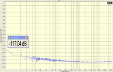
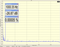
Here, the first result, the noise floor with 50 Ohms at each inputs, differential mode, DC coupling, HPF ON, FS=48kHz (the ADC don't allow 44.1kHz)
The ADC is powered with +/-15V JRS06 PSU from P.Sjöstrom.
Digital output used is coaxial, go to SPDIF input of ESI Juli@ sound-card, ext clock mode.
FFT analysis software :Spectralplus Demo with this setup :
Resulting spectrum is below.
AA5381v1noisefloor48k
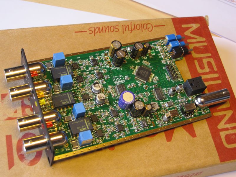
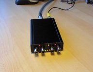
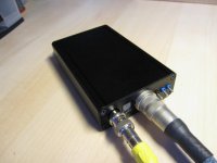
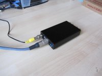
I post some pictures of the converter in it's box.
It's look fine")
Frex.
I start to make measurements with same setup of you.
I will post all detailed result this week end.
Here, the first result, the noise floor with 50 Ohms at each inputs, differential mode, DC coupling, HPF ON, FS=48kHz (the ADC don't allow 44.1kHz)
The ADC is powered with +/-15V JRS06 PSU from P.Sjöstrom.
Digital output used is coaxial, go to SPDIF input of ESI Juli@ sound-card, ext clock mode.
FFT analysis software :Spectralplus Demo with this setup :
- FFT resolution = 1Mpts
- Average=10 (exponential)
- Fs =48kHz
- 0dB of Spectrum is 0dBFS of ADC,
- corresponding to 7.07Vrms for full-scale at the input of ADC.
Resulting spectrum is below.
AA5381v1noisefloor48k
I post some pictures of the converter in it's box.
It's look fine
Frex.
Attachments
New clock.
Hello,
Ghg, yes, i use a 50 Ohms cap on each inputs (in+ and in-).
The noise introduce by them is negligible.
At 48kHz, i reach nearly the spec of CS5381 giving 117dB of noise floor typical (111dB min).
The input buffer used allow to connect very high impedance source,
because the bias current of the buffer is very low.
It's very convenient for a universal measurement tool.
The disadvantage is that OPA134 have slightly higher voltage noise density (8nV/sqrtHz). This explain why the noise floor not reach exactly datasheet value.
In the PCM4222EVM, the input buffer is a OPA1632 fully differential amplifier.
It is a very low noise OPAMP (1.3nV/sqrtHz).
But, if you connect high-Z source, the noise will be much higher because the current noise dominate (In=1pA/sqrtHz) while OPA134 exhibit an extremely low current noise (0.003pA/sqrtHz).
A major problem also with this amplifier is the bias current (6µA max).
When connecting a source with impedance of 100kOhms, the created DC offset is 600mV ! In some applications it can be an issue.
Used this type of amplifier is justified only if the source impedance is always know and very low (less than about 1kOhms).
For the converter IC, it seem that the PCM4222 have performance a little better than CS5381.
When i had designed the ADC, i had need to make a choice .... :b
I just have receive the low jitter TentLab XO, i will mount it in place of the SMD XO. I will continue measurements this week-end.
Frex
Yeah, current noise or voltage noise choice, all depends on the source resistance.
So, for comparison, I added the dual OPA134 ( OPA 2134 ) as a buffer to the balanced input,
switched to 48kHz and did the 1kHz/sweetspot and 50 Ohm differential noise test.
So, for comparison, I added the dual OPA134 ( OPA 2134 ) as a buffer to the balanced input,
switched to 48kHz and did the 1kHz/sweetspot and 50 Ohm differential noise test.
Attachments
Hello,
Thank for those measurements, Ghg.
I don't have done mine.
I don't have a Krohn-Hite or equivalent generator, so i can only test it at 10kHz, using an ultra-low THD "DIY" oscillator.(It is the oscillator described in AN67 from Linear Technology).
This 10kHz generator have 4Vpp output voltage (single ended or 8Vpp in diff mode).
It is powered with same DC source from ADC (JSR06).
I have made measurements with the AA5381 new ADC, and my old design wich use the AK5394A ADC from AKM.
I have find an issue when testing the AA5381 ADC, because the enclosure
had been fully "floating". It degrade the THD performance.
I will fix it this week (adding a direct ground connexion to the box).
I will post all results very soon.
Just in conclusion, my old ADC design outperform all measurements of AA5381..I'm little disappointed...
Frex
Yeah, current noise or voltage noise choice, all depends on the source resistance.
So, for comparison, I added the dual OPA134 ( OPA 2134 ) as a buffer to the balanced input,
switched to 48kHz and did the 1kHz/sweetspot and 50 Ohm differential noise test.
ghg, frex, first, thank you for all these tests.
ghg, I've been considering the pcm4222evm for some time and your results are nice to see. I'd like to ask for a favour please, if you could post the thd+n of the same 48kHz sampling rate and 1kHz/sweetspot. The thd and noise floor of this are quite amazing.
I don't have a Krohn-Hite or equivalent generator, so i can only test it at 10kHz, using an ultra-low THD "DIY" oscillator.(It is the oscillator described in AN67 from Linear Technology).
Frex
I would like to see it, the ultra-low THD "DIY" oscillator. I know of only a couple of them in existence!
I'd like to ask for a favour please, if you could post the thd+n of the same 48kHz sampling rate and 1kHz/sweetspot. The thd and noise floor of this are quite amazing.
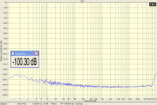
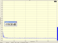
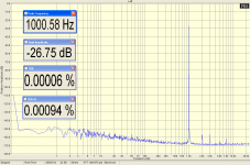
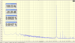
Here we are, and I added a -20dB plot too, according to the datasheet THD+N should be typically -100dB, looks consistent.
@frex: Do you have THD plots of the Williams oscillator on hand ?
An active twin-T would enhance the ESI Juli capabilities to about 140dB resolution @ 10kHz.
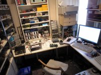
And now I'll have to clean the messy workplace, hardly room for a chair ...
Attachments
jackinnj, i will post this evening a picture of the oscillator.
ghg, I have plot the THD of my 10kHz oscillator with the AKM ADC and the new AA5381ADC. I will post results also this evening.
I have already built a twin-T filter, but I didn't obtain good results.
I will try it again as soon as i will find time...
In any case, you seem to have a nice place to tinker !
Frex
jackinnj, i will post this evening a picture of the oscillator.
Frex
Here's mine:
An externally hosted image should be here but it was not working when we last tested it.
I took a look at the spectrum plots at your site:
DIY Test Equipment for Audio and Ham Radio Enthusiasts
So, 10kHz/5V into TEK, k2 marker gives 567nV at the HP, but where and why was an 20dB attenuator used ? I am confused ...
Maybe you added a +20dB amp after the TEK monitor-out to the HP ?
This would give k2@-119dB ? Impressive @10kHz
Gary
DIY Test Equipment for Audio and Ham Radio Enthusiasts
So, 10kHz/5V into TEK, k2 marker gives 567nV at the HP, but where and why was an 20dB attenuator used ? I am confused ...
Maybe you added a +20dB amp after the TEK monitor-out to the HP ?
This would give k2@-119dB ? Impressive @10kHz
Gary
- Status
- This old topic is closed. If you want to reopen this topic, contact a moderator using the "Report Post" button.
- Home
- Design & Build
- Equipment & Tools
- DIY Analog-to-Digital Converter project.Audio measurements tool