Good to know! however, these bias configurations are particularly for the Panasonic WM61A mic capsules with the 2 & 3 wire Linkwitz mods.
I recently dissected one & found the middle pin (Gate) of the FET was bent to touch the casing (shorted). So in a non modded mic, both the Gate & the Source would be shorted? In the Linkwitz mod, cutting the trace disconnects the source pin from the Gate & casing? In the 2 wire mod you'd actually feed the -9V through a 10Kohm to the Sourcs to bias the FET!. Fig;3
Unlike a BJ Transistors, FET output don't change with increased voltage.This is one the intrinsic attributes of JFETs!
What I'm not sure about is whether grounding the Gate,directly,through a R or a Capacitor?
Last edited:
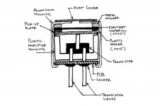
As you can see on the following picture from the link you provided, the gate is not accessible from outside:
http://www.openmusiclabs.com/wp/wp-content/uploads/2011/03/mic_section_med.jpg
It is the center pin of the FET, touching the insulated pickup plate.
http://www.openmusiclabs.com/wp/wp-content/uploads/2011/03/mic_section_med.jpg
It is the center pin of the FET, touching the insulated pickup plate.
3M EMI copper foil tape is sold as having conductive adhesive. I think I read it has tiny copper spheres in the adhesive. I have used 'termite barrier' copper which is much thicker, for guitar shielding. The brand I used (can't recall, it's from a company in Maine that also makes 'too-thick-for-tape' flashing copper) has a non-conductive rubber-based adhesive.
Looking through a Digi-Key catalog, I see there are some ECM capsules that have gold-plated brass bodies, which would solder easily, with the same heat precaution.
I use a microscope to see the 'patient' ECM.
Now, my question -
I have three Kodak point&shoot digital cameras with usable video (2 are low-end HD) and horrible audio. One died and the the other two went 'Andy Warhol' - crazy colors. I found a service manual for the dead one on a Russian website and tore it apart with no intention of re-***'y.
Of the two semi-functional cameras, I got one running with correct colors with a couple whacks to the side (like an old TV), which has me wondering about ribbon cable connectors etc, internally.
I have never gotten a digital camera apart and back together previously. However, I took camera #3, got it apart without breaking anything (photoflash cap is discharged as well), and have the ECM hanging out now. It's tiny(maybe 4mm diam. 1.5 mm height?), 2-wire, and appears to be one of the gold-plated ones.
I will look again, but the SMT parts are so small on the circuit board where the ECM wires go that I doubt the resistors will have values on them (0402 or smaller usually do not).
So I am going to gamble that the service manual for the least expensive one that wore out & was disassembled has a similar bias circuit. I'll triple check what ASIC-type device the ECM feeds...I think they might not even be the same among the three cameras..but one for which I have a schematic has an 'isolated' 3V analog audio supply fed through a 22k resistor. There is a 1 uF (as best I can read the blurry schematic) X5R cap coupling audio and blocking DC at the (Altek?) audio processor.
So, assuming the camera I want to mod the mic on also has a 22k resistor feeding the drain, my feeling is adding a 22k source resistor probably has the lowest risk of running into headroom problems due to Vgs characteristics of the ECM jfet. OTOH, if you look at datasheets for jfets made for this app, many have very low Vgs(off), (and typically a 1 mA max drain current, BTW).
I considered drilling a hole where the mic sound hole was and running the wires outside to try different resistors or even an outboard modded mic, but I want to be able to get it back in the case (one time surgery) and through airport scans. I've not have good luck with wires hanging out of things...they tend to catch TSA attention.
Anyone agree or disagree with making Rs the same as the existing in-camera Rd? I want to minimize mods and poking around to anything past the ECM, as I'm already pushing my luck having gotten it apart without tearing any flex PC wiring etc.
I might try, if successful another one with an ECM I got off a toy Intel Voice Morpher. It had a larger capsule, roughly 8 mm diam mounted in a parabolic reflector!
The goal is make the camera audio usable. It currently is not. If I wanted higher quality and less portability I'd look at a separate audio recorder...and learn how to recombine audio & video...or buy a standalone video recorder that does the job adequately...but I'm not at that point yet.
Thanks
Murray
Last edited:
I was able to cut the trace on the 3-4 mm diam. ECM (I had no choice but to unsolder the PCB side to give myself working room (1.5-2" leads)...I couldn't do it without the ability to hold the ECM on a flat surface. An Exacto blade was way too big! I used a really fine needle to scrape through the trace, while holding the body with fine tweezers.
The two ECM PCB traces are marked '+' and 'E'. I took E to mean earth...just to make some sense out of it. Now I have to find a resistor small enough...looks large under a microscope, but I realize I have significantly less than half the ECM diameter...so an 0603 resistor I can read the numbers on is relatively huge. The next couple sizes down are so small I'll probably need more than one resistor in case I lose some...I have lost 'duct-sized' parts before...I scraped solder mask off the areas I'll solder the resistor to...as far apart as I could to give me options for what size resistors I can find.
I'll be amazed if I pull this off...I mean get it back together still working...at least it's still promising no sudden-death failures have become evident yet.
Last edited:
Here is a schematic og WM61 capsule wired for balanced input! The entire article can be found on
Suite101.com: Online Magazine and Writers' Network
PSlease note that the "Caps" are drawn wrong,but the orientation is correct!
Hi folks,
My first post here, I've lurked on and off for years but figured I'd sign up today to pick your brains! Sorry if this isn't really the right place to ask these questions, but it's specifically about this capsule so..
I do a bunch of DIY Audio stuff, but not quite on the level of you lot. Take a look if you like: Gallardo Sound.
So, I built the circuit (two of them in fact) I quoted up there this morning, so I can power a binaural dummy-head using the WM61As from phantom power. It reads at 12v where the mic connects, and for all intents and purposes it works, having tested it via my usb interface. There's a very strong buzz, but that's another question really.
My main question is, will that circuit work with the Linkwitz mod? I want to be able to use the dummy-head at gigs, and I understand I'll need to do the mod to avoid distorting the capsule. My secondary question is, is the Linkwitz mod really necessary for recording gigs?? I did manage to distort the capsules with the head located about a foot from a crash symbol, but it seemed to handle my mate bashing seven shades out of the kit.
Sorry for barging in with my decidedly amateur questions!
Here is one for Scott (Wurcer).
I hope you are watching.
Patrick
I don't see much new here. Did I show that little circuit with just two bipolars and capsule? It gets as much out of a WM61 as possible, "distortionless" output of volts and no added noise. I sort have gotten tired of explaining that you can't improve the noise except maybe by cutting away the baffle which grossly effects the flatness. People still put in a 2SK170 which makes the noise worse, the WM61 is just too small.
BTW electret microphones do not require an external bias, these guys are very confused. I also disclosed the feedback via the cut pin on the capsule on the micbuilders site years before this, didn't see the point of including it in the article because the capsule where the case is an input is hard to use. Zap or Eric could confirm that.
Last edited:
Unfortunately Panasonic exited the mike business, The WM61A is passing into history. Someone needs to find a successor. For flatness ST has some new MEMS mikes that are quite good with extended low frequency response. The SNR is very limited though. MEMS microphones - STMicroelectronics
Panasonic and another question
I have a catalog downloaded on another PC from another company that I found after extracting an ECM capsule from something I tore apart. They have a very broad line with cross references to Panasonic and other mfrs.
I'll come back & post it.
Actually, I think I'll start a new question because the capsule's I'm working on are neither brand.
- Status
- This old topic is closed. If you want to reopen this topic, contact a moderator using the "Report Post" button.
- Home
- Design & Build
- Equipment & Tools
- Linkwitz Mods On Panasonic WM61A Mic