Hello all.
An idea I have been toying with for a long time is gutting my computer monitor (CRT) and replacing as much of the circuits as possible with discrete analog circuits of my own design.
The first thing I thought about was the sweep generator for the monitor. For this application, the sweep needs to be decently accurate, to keep image distortion minimal. That's what I want, at least. I'm just an angsty teen but I get annoyed when the edges of the picture aren't straight.
From concept to substance will take time for the entire project, but I decided to post here to see what requirements a DIYer has for the minimum accuracy of a saw wave generator. My default minimum here is a sweep that looks graphically perfect when viewed with, say, an oscilloscope.
However to get further the only method I know of is to use FFT analysis. Ideally a saw wave has all harmonics at correct proportions.
So, to all which it applies, what requirements would you require be met before you stamp an analog sweepgen circuit with your personal seal of approval, and perhaps use it in your own projects?
- keantoken
rising sawtooth
is one of the most useful signals for testing amplifiers
what is Rising Sawtooth Wave?????
the rise is the same as rise of one square wave
the sloop is the same as of triangle wave
... then it repeats with a 90 degrees rise again
using this for oscilloscope testing, you get alot of good information
Try it, and you will see what i mean")
is one of the most useful signals for testing amplifiers
what is Rising Sawtooth Wave?????
the rise is the same as rise of one square wave
the sloop is the same as of triangle wave
... then it repeats with a 90 degrees rise again
using this for oscilloscope testing, you get alot of good information
Try it, and you will see what i mean
i have one schematic for making the sawtooth
that i described in prev post
it is from one Elektuur article way back
I even have made my own sawtooth generator circuit.
1. You have to use very fast switching transistor for the rising square.
High slewrate, low rise micro seconds value of transistor.
2. Then you have one capacitor to detect the top limit
and begin the 'slow' sloop until another lower limit
which will trigger
3. the fast rise transistor again
Not too difficult or complicated to do discrete with a handful of suitable transistors.
I took what transistors I had in
my personal re-use supply = desoldered from old PC and radio circuits.
And it worked pretty well, even if those transistors was not the same as in Elektuur article.
Lineup - Electronical wave generator circuits.
Only for his members signed up
Nothing much to see for anonymous 'Guests' & Other
I just registered, Lineup.
I didn't find the circuit, though...
At any rate, here's what I know about analog sweep generators, of the cap-charge variety:
1: Cap must be fed with a good CCS, with low Cj transistor, which is especially important at high frequencies.
2: Discharge device should draw as little current at idle as possible, to keep constant current through the capacitor.
3: good cap is needed. Electrolytics aren't required. 60Hz can easily be made with a 100n cap.
4: if output is connected directly to charging capacitor, it must be a VERY high-impedance amp or other. From what I know, CRTs have basically infinite impedance, so perhaps the CRT plates can themselves be used as the capacitor.
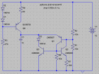
That said, here is the circuit I've been messing with for a while. Once I have the parts and time, I will attempt to build it. It simulates fairly well.
Q1 and Q2 for a PUT pair/SCR thingy, which CAN be run without Q3. However, this limits the high frequency possibilities. Without Q3 the highest is about 20KHz and if you're lucky 40KHz. With Q3 it is possible to go in the 100's of KHz with still decent waveforms.
In certain situations bypassing R7 a 10p cap will help if you can't get it to start. Putting a small resistor in series with the capacitor may help in some situations as well.
Frequency is easily controlled via R4, which can be some sort of POT.
Unfortunately, the PUT pair relies on Q1's Vbe to fire at the right voltage, so unless some kind of frequency locking/compensation/correction is implemented, it is perhaps not suitable for use in the freezer or oven.
As should be expected, all devices should have low Cj and high gain is beneficial.
A two-transistor arrangement was tried for the CCS, but the current arrangement is now used because of lower parasitics.
R5 keeps idle current draw from Q1 and Q3 minimal, but it can be higher, say 100K or 1meg.
Overall, it is a very simple circuit. However, for different needs it may need to be adapted. HF performance and harmonics can be improved most easily by inserting small resistor values in certain places bypassed with a 10p cap. Various tweaks can be made Via HF coupling in order to make the edges of the sweep sharper (=more HF harmonics). A 10p across D1 might help edge sharpness a bit.
Currently, output must be taken from Q1's emitter, which may cause problems. I have not found a suitable Hi-Z impedance matching solution for this.
At any rate, I hope it deserves my descripion, enjoy.
P.S.
D3 can be omitted and replaced in series with R2 so the circuit will give full 0-6V sweeps instead of 0.6-6.6 (or whatever set by the ratio of R2 and R1). However, if a bipolar NPN is hooked up to sample the output, the 0.6V boost is helpful.
- keantoken
I didn't find the circuit, though...
At any rate, here's what I know about analog sweep generators, of the cap-charge variety:
1: Cap must be fed with a good CCS, with low Cj transistor, which is especially important at high frequencies.
2: Discharge device should draw as little current at idle as possible, to keep constant current through the capacitor.
3: good cap is needed. Electrolytics aren't required. 60Hz can easily be made with a 100n cap.
4: if output is connected directly to charging capacitor, it must be a VERY high-impedance amp or other. From what I know, CRTs have basically infinite impedance, so perhaps the CRT plates can themselves be used as the capacitor.
That said, here is the circuit I've been messing with for a while. Once I have the parts and time, I will attempt to build it. It simulates fairly well.
Q1 and Q2 for a PUT pair/SCR thingy, which CAN be run without Q3. However, this limits the high frequency possibilities. Without Q3 the highest is about 20KHz and if you're lucky 40KHz. With Q3 it is possible to go in the 100's of KHz with still decent waveforms.
In certain situations bypassing R7 a 10p cap will help if you can't get it to start. Putting a small resistor in series with the capacitor may help in some situations as well.
Frequency is easily controlled via R4, which can be some sort of POT.
Unfortunately, the PUT pair relies on Q1's Vbe to fire at the right voltage, so unless some kind of frequency locking/compensation/correction is implemented, it is perhaps not suitable for use in the freezer or oven.
As should be expected, all devices should have low Cj and high gain is beneficial.
A two-transistor arrangement was tried for the CCS, but the current arrangement is now used because of lower parasitics.
R5 keeps idle current draw from Q1 and Q3 minimal, but it can be higher, say 100K or 1meg.
Overall, it is a very simple circuit. However, for different needs it may need to be adapted. HF performance and harmonics can be improved most easily by inserting small resistor values in certain places bypassed with a 10p cap. Various tweaks can be made Via HF coupling in order to make the edges of the sweep sharper (=more HF harmonics). A 10p across D1 might help edge sharpness a bit.
Currently, output must be taken from Q1's emitter, which may cause problems. I have not found a suitable Hi-Z impedance matching solution for this.
At any rate, I hope it deserves my descripion, enjoy.
P.S.
D3 can be omitted and replaced in series with R2 so the circuit will give full 0-6V sweeps instead of 0.6-6.6 (or whatever set by the ratio of R2 and R1). However, if a bipolar NPN is hooked up to sample the output, the 0.6V boost is helpful.
- keantoken
Attachments
keantoken said:
4: if output is connected directly to charging capacitor, it must be a VERY high-impedance amp or other. From what I know, CRTs have basically infinite impedance, so perhaps the CRT plates can themselves be used as the capacitor.
If you're modding a computer monitor then it will have deflection coils. Low impedance inductors that have to handle flyback.
I have to ask, is this just for the education? Even if you vastly improve the drive electronics, it's still only a 1024 x 768bit, 0.25mm pixel display. There's been some pretty smart guys working on CRTs over the years, I think it will be hard to do better.
wrt sawtooth, if you have a PC w/ soundcard just make a wave file where each sample increments/decrements by a fixed amount (i.e. a counter) and play that. Should be accurate to -96dB (theoretically) with no switching artifacts.
There's been some pretty smart guys working on CRTs over the years, I think it will be hard to do better.
I'm fairly certain that with the advent of the microchip, and cheap IC sweep generators, with bad capacitors hooked up to them, I don't know that it takes a smart guy to build a bad monitor nowadays. All I know is that I'm not satisfied with most of my monitors, for these reasons:
1: the picture distorts when there is a bright spot on the screen. I can watch the screen enlarge as it gets brighter. I have an old IBM monitor and this doesn't happen.
2: contrast and brightness vary with screen content, sometimes making it illegible.
3: Black level adjustment does not work.
None of these are related to Gamma settings, although they could all just be related to bad caps and poor power supply. At any rate, maybe you're luckier than I am with monitors.
About using the soundcard, I would just rather not. I also doubt very seriously that I would get that perfect quality without paying $$. It seems like a cheap solution to me, and in any case, I'm happier designing my own equipment.
Yes, this is a lot for the education. However if I'm going to design a good circuit I'm not just going to put it in this project and forget about it. Hopefully I'll have a lab buddy out of this.
I didn't think about the deflection coils... Hmm.
Thanks for the advice. I do want to at least get through this thread with a good and simple sawtooth circuit.
- keantoken
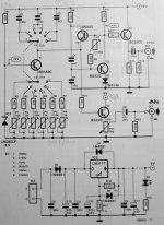
You have this DIY project
with some EEPROM programming
Universal Digital Function Generator
http://www.geocities.com/dsaproject/electronics/f_gen/f_gen.html
Here is the schematic:
http://www.geocities.com/dsaproject/electronics/f_gen/udfg_sch.pdf
You also have the Layout + Parts list for this project
in the link above.
with some EEPROM programming
Universal Digital Function Generator
http://www.geocities.com/dsaproject/electronics/f_gen/f_gen.html
Here is the schematic:
http://www.geocities.com/dsaproject/electronics/f_gen/udfg_sch.pdf
You also have the Layout + Parts list for this project
in the link above.
Sorry to bring doom and gloom but you will never do it. The deflection currents for a CRT are not linear but are modified to allow for correction of geometry. At the most basic level you need to introduce N-S and E-W correction as well as pincushion correction. All done by modifying the line and field current in the deflection yoke away from the ideal sawtooth.
I would suggest you read up on television receiver theory.
You image "enlarges" on bright scenes because the EHT drops due to poor regulation. As the EHT falls the electron beam becomes easier to deflect so the picture goes bigger.
Try something less ambitious
I would suggest you read up on television receiver theory.
You image "enlarges" on bright scenes because the EHT drops due to poor regulation. As the EHT falls the electron beam becomes easier to deflect so the picture goes bigger.
Try something less ambitious
- Status
- This old topic is closed. If you want to reopen this topic, contact a moderator using the "Report Post" button.
- Home
- Design & Build
- Equipment & Tools
- What would be your requirements for a discrete saw wave generator?