Am I correct that a volt meter connected to one green and one blue lead should net me 12volts AC?
I would love suggestions on whether the greens or the blues go to the A terminals and which to the B terminals
Yes.
Doesn’t matter at all, but be consistent on both sets of terminals.
Hello Forum Members,
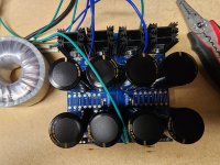
Correct me if I'm wrong but I think I have a successful, functioning PSU.
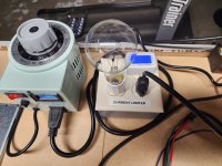
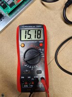
I placed a variac and dim-bulb tester in-line to be safe. I used a 100VA transformer with 12V secondaries to power up the PSU. As I dialed up the variac, the DC voltage on the output terminals increased smoothly. I neglected to test the AC secondaries to confirm that they were supplying exactly 12 volts. However, with the variac supplying 110 Volts AC to the unit, I measured +15.1 vdc and -15.1 vdc as expected from 12 volt secondaries. Additionally, both LED's light up. Any concerns? I attached a couple of pics. Also, I had 10k 1w resistors as load on the output. Thank you.
Correct me if I'm wrong but I think I have a successful, functioning PSU.
I placed a variac and dim-bulb tester in-line to be safe. I used a 100VA transformer with 12V secondaries to power up the PSU. As I dialed up the variac, the DC voltage on the output terminals increased smoothly. I neglected to test the AC secondaries to confirm that they were supplying exactly 12 volts. However, with the variac supplying 110 Volts AC to the unit, I measured +15.1 vdc and -15.1 vdc as expected from 12 volt secondaries. Additionally, both LED's light up. Any concerns? I attached a couple of pics. Also, I had 10k 1w resistors as load on the output. Thank you.
Attachments

Correct me if I'm wrong but I think I have a successful, functioning PSU.
I placed a variac and dim-bulb tester in-line to be safe. I used a 100VA transformer with 12V secondaries to power up the PSU. As I dialed up the variac, the DC voltage on the output terminals increased smoothly. I neglected to test the AC secondaries to confirm that they were supplying exactly 12 volts. I measured +15.1 vdc and -15.1 vdc as expected from 12 volt secondaries. Additionally, both LED's light up. Any concerns? I attached a couple of pics. Also, I had 10k 1w resistors as load on the output. Thank you.
Looks Good .Using a transformer with 12 Vac secondaries , Vout = 15.8Vdc = ( 12 v x 1.414 ) - 1.2 Vdc
would be expected . The secondary output voltage of the transformer will drop as the load current increases .
Keep in mind , that regardless of the transformer used , it will still take 5 x Tau for those caps to discharge .
.
Thanks for commenting on my post @Uunderhill. I think I'm in business as far as the PSU is concerned.
I will definitely keep the x5 Tau formula handy regarding the safe discharge of caps. I don't think one can be "too safe" when protecting life and limb. I purchased a rubber mat to stand on, and industrial rubber gloves for use when adjusting and testing live assemblies. I'm also very aware of the old axiom of keeping one hand in your pocket when probing.
I wanted to Thank you and everyone else in this forum that provided me with patience, expertise and advice. I really appreciate it.
Many successful builds to all of you.👍
Quick question from a new guy...Why does everyone seem to use terminals and crimping on PSU's rather than just soldering the wires directly? Thank you...
Keep in mind there is quite a bit of current involved here . So just the slightest hint of resistance in the termination or wiring can cause a voltage drop .
I was prototyping an amp with about 40 cm of 18 awg (?) lamp cord between the amp and a DIY CRC power supply .
With a bias current of 1.3 Amps , the voltage drop across that bit of lamp cord was 12mVdc .
So that's about 9 mOhms . Which doesn't sound like much , but putting this into perspective
those big electrolytic caps will have an ESR of something in the neighbourhood of 20 mOhms .
Then 2 parallel on the output gives 10 mOhms . So the termination and wiring could mess up all the effort
gone into having a low impedance on the output of the power supply .
So either solder , or use those disconnects UncleMud used - but with these kinds of currents IMO forget those screw terminal blocks .
Between the power supply and the amp and speaker terminals , I'd say use 12 awg minimum .
Also , use star grounding .
.
as a diyer, always tinkering with things. The quick connects and screw-down terminals make life so much easier. In fact, about to take my F4s back apart to put in Gian Luca's new heatsink frames. (hoping this gets rid of the thermal ping from something on the chassis shifting as it heats up).
Hello Forum Members,
Earlier in this thread I successfully tested my V3 board with a 12v transformer using 10k 1 watt resistors as a load. I would like to test the unit now that I have connected the recommended toroid to the PSU. The transformer is a 625VA model with dual 45v secondaries.
Will the same resistors be appropriate for testing, or will I need a more rugged option?
Are you referring to the filter resistors (the R in the CRC)? What wattage are you using and what is the end load expected?
What is the VDC ratings on the capacitors? As you're jumping up to 45V secondaries, you're going to want 75V rated or higher. 45VAC after rectification is about 64VDC (1.414*45).
What is the VDC ratings on the capacitors? As you're jumping up to 45V secondaries, you're going to want 75V rated or higher. 45VAC after rectification is about 64VDC (1.414*45).
Hi 6sX7,
Thank you for your response. Sorry I wasn't more specific. The capacitors are actually 80vdc KEMETs.
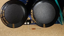
The resistors I was referring to were resistors placed from the outputs to ground as a load when testing the PSU to make sure it is working properly.
Although I successfully tested it at a lower voltage, I thought I should also test a full voltage before further assembly. I've attached a pic for visual reference.
Thank you for your response. Sorry I wasn't more specific. The capacitors are actually 80vdc KEMETs.
The resistors I was referring to were resistors placed from the outputs to ground as a load when testing the PSU to make sure it is working properly.
Although I successfully tested it at a lower voltage, I thought I should also test a full voltage before further assembly. I've attached a pic for visual reference.
Attachments
V=I*R;
W=V*2/R
Don't really need the resistor to test the PSU. Just measure if you have 63VDC at the output pads.
With the resistor as a "dummy" load, using the above Ohms law and Watts equation calculate how many watts that 10k Ohm resistor will be dissipating. Use a larger wattage resistor or higher resistance if the power dissipation is expected to exceed 1W. I did a quick calc and came up with 0.4W dissipation expected. Should be fine but as mentioned earlier, don't really need it to check if the PSU is working correctly.
With the 45V transformer, you can first test the power supply without a load at the output. If you want to be extra careful, you can do your first power-up with a Dim Bulb Tester (DBT). If that is successful, then power up without the DBT. Without a load the output will be a few volts higher than the expected voltage under full load.
As for testing with a load resistor, unless you have some very high wattage resistors mounted on a heat sink, you will not be able to test to full capacity of the power supply. But if the power supply powers up successfully with the 45V transformer, then you are most likely good to go.
What values of resistor do you have for the bleed resistor and LED resistor? Note that your power supply is more than double the typical First Watt supply voltage so adjustments need to be made to those resistors.
Hi Ben Mah,
Thank you for your response. In looking at my construction records I believe the LED dropping resistors are 60.4k 1 watt. According to my notes I used 22k 3 watt flame proof resistors as bleeder resistors.
Thanks for your advice on testing my PSU, I appreciate your time.
Thank you for your response. In looking at my construction records I believe the LED dropping resistors are 60.4k 1 watt. According to my notes I used 22k 3 watt flame proof resistors as bleeder resistors.
Thanks for your advice on testing my PSU, I appreciate your time.
- Home
- The diyAudio Store
- V3 Universal Power Supply Circuit Board