Herman,
He's designed it, "The Equal Opportunity"
Published in Linear Audio in two parts - 1) https://linearaudio.net/article-detail/2170 2) https://linearaudio.net/article-detail/2206
And here's the diyAudio thread - http://www.diyaudio.com/forums/analogue-source/256062-equal-opportunity-mm-pre.html
I'm building one, slowly. You have to get the articles from Jan. There might be a set or two of PCB still floating around.
Last edited:
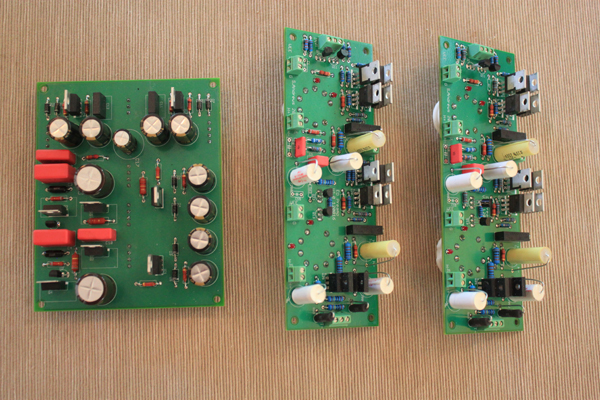
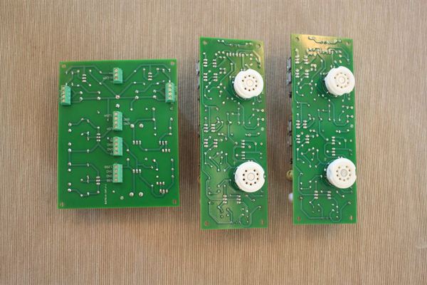
I am building the EO preamp as well. I decided to do my own boards because of the physical layout I wanted. So, I have the signal components and the CCS's on two identical boards with the tube sockets on the opposite side from the components (so the tubes can protrude through holes in the chassis), and I have the power regulator circuits on a separate board that is mounted a couple of inches away in a vertical setup so the big regulators all have convection cooling. The chassis top and vertical section is done with mirror finish stainless, so the tubes will be nicely showcased. The rest of the "chassis" is varnished teak, and there is a perforated cover to protect the supply while allowing for convection cooling. It is about 90% done.
I started by collecting parts for the HMN preamp, and then, like noviygera, realized I wanted to do an MM design. So, the power transformer I had was wrong (too high a secondary and no separate tap for the negative supply. I built it up anyway thinking that Sy's statement "the higher the better" in terms of regulator overhead would save me, but then I realized that later in his article he pointed out that at 16 mA, the overhead can't be too high before the heat dissipation in the regs becomes too high. Edcor does make one that works, but it is a special order. Not too expensive, but 6 week lead time!!! This modified raw supply should produce about 165 volt B+ rail, and an 18 volt B- rail.
I'll post pics of the build in a few days.
Scott
Last edited:
Herman,
SY is on a vacation from diyAudio. While not speaking for him, what SY did do was design an MM phono preamp. There are two articles in Linear Audio volumes 7 and 8 for the Equal Opportunity MM Phono Preamp. There is also a thread here in diyAudio started by jackinnj.
I found it very interesting to read both the "Majesty's Noise" and the "Equal Opportunity" because he clearly explains his design philosophy and the differences in approach between the MC and MM.
It takes some looking, but I found I could buy just the articles from Linear Audio on their website.
By the way, I'm one of the guys that built the EqOpp preamp and love it.
Jac
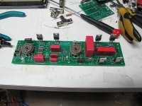
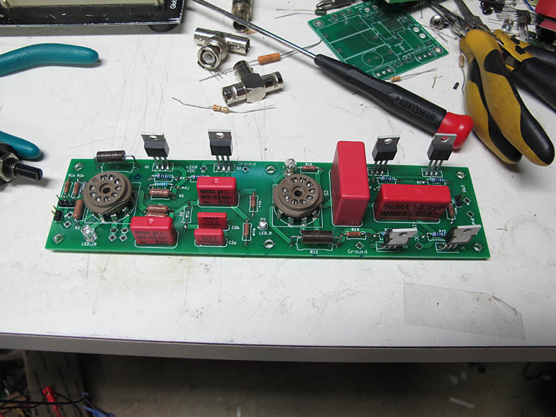
Here are my boards for the EO preamp. I'll start a new thread on this so we don't drift this one.
As noted, I put the tube sockets on the top of the boards, and put the components on the bottom. This allows me to have the tube sockets poke through holes I cut in the stainless top plate of the chassis, and allow room for the somewhat large components. The tubes will thus show, while the boards won't.
Once I test this, I'll post the board artwork so that anyone can get the boards fabbed. They were pretty expensive in small quantity (about $60 each), but they are very nice quality. I did the layout in Eagle. Signal boards on the right, regulator on the left..
Scott
Hi,
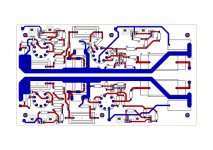
could somebody take a look to my design? Are there correction needed? Or have someone an idea for improvements?
The board is 240x140mm cause it has to fit an empty cabinet in my Hovland HP100. I bought the Hovland used, without Phono Amp.
The design is not symmetrical. So its possible to put the GND of both Channel together if needed. Is this okay?
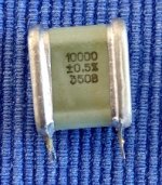
i would use Glimmer-capacitors for the 32nf-capacitor. The board can be fitted with Wima, Mundorf or Hovland capacitors.
The connection for the tube filament will be soldered directly at the sockets.
Thanks for your help.


could somebody take a look to my design? Are there correction needed? Or have someone an idea for improvements?
The board is 240x140mm cause it has to fit an empty cabinet in my Hovland HP100. I bought the Hovland used, without Phono Amp.
The design is not symmetrical. So its possible to put the GND of both Channel together if needed. Is this okay?
i would use Glimmer-capacitors for the 32nf-capacitor. The board can be fitted with Wima, Mundorf or Hovland capacitors.
The connection for the tube filament will be soldered directly at the sockets.
Thanks for your help.
Attachments
Last edited:
Ive ordered my new turntable and cartridge. Ive gone for a gyrodec se with a benz micro wood SL.
This is quite a bit hotter than the cartridge in the article.
its a 12ohm resistance and outputs 0.4mV at 3.54cm/s which i believe translates to about 0.56mV at 5cm/s
Im under the impression that His masters noise give about 68db of gain based on 0.2mV input producing 0.5V output.
I think i want about 59db with this cartridge to get to 0.5V output. Im sure a bit more gain would also be ok.
I dont think this would overload anything in the circuit as it seems theres plenty of headroom but it may well be a tad hot on the output, about 1.4V. I dont think my impasse input tx would mind this but im then going to end up attenuating it quite a lot on the volume control. This seems daft.
The sowter 1480 (replacement for the 8055) can either be used as 1:5 or 1:10
1:10 gives 20db gain
1:5 about 14db.
This would give me most of the reduction in gain to essentially match the 0.2mV example in the article ensuring no overloading anywhere.
It seems that if i can get more clean gain from the input tx that would be preferable and just add less gain later. The D3a would still be seeing fairly low voltages.
Can this be done by altering the 1k plate resistor R12?
Suggestions? even if going for a totally different phono stage.
Regards
D.
Dave,
First of all, I am very far from expert at these things. But a couple of thoughts.
As I understand it, signal transformers change bandwidth depending on trafo gain and the load impedance following the trafo. As you consider trading off input trafo gain against amplifier gain, make sure you understand the bandwidth and noise implications for the trafo.
In other words, for a non-expert like me, I worry about the unknown tails that a change in the design creates. It seems like turning down the volume control is low risk by comparison. SY designed a high gain preamp with good noise immunity, so you aren't paying a price for the high gain as designed.
However, having said that, I do go ahead and take those risks, even when it's ill advised. Of course, I try to chase the tails all the way through the system, but I'm sure I don't understand every tradeoff. Maybe that's part of the fun.
Jac
Hi jac, thanks for the response. I have looked at the loading info on the Rothwell site and as the 8055 has been superceded I would use the 1480. I would also build the test rig to check the loading. I worked out that around a minimum 3k should give suitable loading when the tx is set to 1:5. Without loss that gives me 2.8mV and with the loss due to the potential divider being set up with the cart impedance and the input load to give about 2.5mV on the output of the tx.
I haven't calculated the loss for the example cart. Maybe it's in the article. Can't remember off the top of my head but iirc about 1db down from 2mV.
I think bandwidth tends to be more of an issue with higher ratio transformers.
Maybe I'll build it stock with the 1480 at 1:10 with adjusted loading and see what happens. If nessesary I suppose I could add a potential divider between gain stages with some high grade resistors but I would have to research how do do that correctly. I think the impasse did something like that.
I believe SY designed in more than sufficient headroom to accommodate your cartridge and the recommended (or replacement) SUT. A lower gain SUT such as the 8X LL1931 might be an option. I would not modify the circuit unless you understand the design intent since unpredicted consequences like incorrect EQ, increased noise and distortion are likely consequences of some of the changes you propose.
I generally design my phono stages to produce outputs with the intended cartridge and transformer in the range of typical red book CD players or DACs which is 2.0Vrms at 0dBfs. I think SY intended something similar in this design, but it has been a while since I last talked to him about it.
I generally design my phono stages to produce outputs with the intended cartridge and transformer in the range of typical red book CD players or DACs which is 2.0Vrms at 0dBfs. I think SY intended something similar in this design, but it has been a while since I last talked to him about it.
Kevin, thanks, that's great to know.
I'll try it at 1:10
Wierdly my current atoc3 which is 0.35mV (not sure whether 3.54 or 5cms) in to a 55db preamp was only a bit quieter than my dac for the same cd/record, of course that's very non scientific as I know the dc isn't particularly hot and maybe the record was.
Still, I have the dilemma of whether to rewire my rb300 to balanced operation. I bought the better cartridge instead of upgrading to an audiomods at the same time. I'll probably leave as is until I can build the hmn then reasess.


100db anything seems pretty good to me! I wish my scope was that quiet. Think i need to get a better one.
So is your input signal a simulation before transformer at about ~0.2mV or post transformer straight in to the input on the board at ~2mV? 100db down from that seems insanely low noise, amazed thats even possible.
So is your input signal a simulation before transformer at about ~0.2mV or post transformer straight in to the input on the board at ~2mV? 100db down from that seems insanely low noise, amazed thats even possible.
- Home
- General Interest
- diyAudio.com Articles
- His Master's Noise: A Thoroughly Modern Tube Phono Preamp