Hi ywh,
Here's a few things about ballast opto-couplers that some people might find useful....
I have a Sanyo PLC-XW15 projector which has been sitting here for months. It has a Philips ballast though, a photo is attached (can you attach more than one file?)....
The projector itself is faulty because the main BGA scaler chip (Pixelworks) had to be de-soldered from the board. The previous owner had tried to re-solder it before for some reason (probably bad connections), so now, I can't re-solder it without getting a new chip, or getting the old one "re-balled". I'll probably sell the projector on eBay again!!
I was able to test the ballast though by shorting the optocoupler (like you do on your ballast). To find out which pins I needed to short, I first hunted down the datasheet for the optocouplers, then traced which pins on the connector joined to which pins on the optocouplers. Please note that not all optocouplers have the same pinout!! The pins on each end are sometimes swapped....
The Sanyo projector (Philips ballast) has the code SFH6106 on the optocouplers, so I just did a Google search to try to find the datasheet. The SFH6106 is made by many manufacturers, but here's a datasheet from Vishay.....
http://www.vishay.com/docs/83666/83666.pdf
You can see that all an optocoupler (or "opto-isolator" or "photocoupler") is, is simply an LED and a phototransistor separated by a gap. This effectively isolates the high voltages of the ballast from the rest of the projector's electronics. This is important, because not only is an e-ballast very electrically "noisy", the ground levels are often at a different voltage to the rest of the projector, so it's quite difficult to connect anything between them. Optocouplers are the safest way of sending signals to and from the ballast.
So, once you've found the pinout of the optocouplers, you can see that where the LED side (Anode and Cathode) connects to the cable from the projector, this is a signal TO the ballast....
And where the phototransistor side (Emitter and Collector) connects to the cable from the projector, this is signal TO the projector.
If you just want to get a ballast to start, you should be able to short the Emitter and Collector pins of the optocoupler(s) on the ballast "side".
If you're trying to retrofit a new ballast / lamp into a working projector, on MOST projector's, you should be able to just short-circuit the Emitter and Collector pins of the optocoupler(s) (going towards the cable) to tell the projector that the "lamp is lit" or "lamp is OK". The problem is finding which optocoupler does what when there are more than two of them!
If you can find the service manual for your projector, then you're very lucky (InFocus X1 is easy to find), if not, then a bit of guesswork is needed...
You could just try shorting the Emitter and Collector of each optocoupler and see what happens, but some signals might be "error" signals to the projector, so it will just shut down.
It helped me alot by soldering LED's between the Anode and Cathode pins of the optocouplers on my Proxima DS1. You should really have an Oscilloscope for this type of stuff, but mine broke a long time ago! xeye: I will attach a photo of the Proxima DS1's optocouplers in the next post.
btw: Anode = Positive,
Cathode = Negative...
If the LED's don't light up when you turn the projector on, you might need to solder one leg of the LED's "before" the resistor which is usually in series with the optocoupler (see photo in next post). That's assuming your LED's can take the current!
After I'd done this, my LED's then lit up when the projector was started. I have two pairs of optocouplers on my Proxima, but I could see that while one LED turned on solidly, the other one seemed to flash in sympathy with the colour-wheel (got quicker faster until almost lit solidly). This is obviously the "sync" signal to the ballast. The ballast needs this so it can syncronize the pulses of voltage to the ballast in time with the colour-wheel and the "frames" of video on the screen. Otherwise, you'd get flickering effects and "tearing" of the video.
AFAIK, some LCD projectors have a "sync" signal to the ballast, but I think it's more important on DLP projectors.
So, for the moment, I didn't need to use the sync signal on my Proxima, as I'm intending to fit a new ballast and power supply to it (the old one is beyond repair, I also want cheap lamps!). I might need the sync signal for the new ballast though, so this is handy to know.
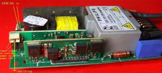
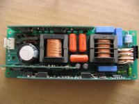
@ywh, here's a photo of the Philips ballast from the Sanyo PLC-XW15.....
Here's a few things about ballast opto-couplers that some people might find useful....
I have a Sanyo PLC-XW15 projector which has been sitting here for months. It has a Philips ballast though, a photo is attached (can you attach more than one file?)....
The projector itself is faulty because the main BGA scaler chip (Pixelworks) had to be de-soldered from the board. The previous owner had tried to re-solder it before for some reason (probably bad connections), so now, I can't re-solder it without getting a new chip, or getting the old one "re-balled". I'll probably sell the projector on eBay again!!
I was able to test the ballast though by shorting the optocoupler (like you do on your ballast). To find out which pins I needed to short, I first hunted down the datasheet for the optocouplers, then traced which pins on the connector joined to which pins on the optocouplers. Please note that not all optocouplers have the same pinout!! The pins on each end are sometimes swapped....
The Sanyo projector (Philips ballast) has the code SFH6106 on the optocouplers, so I just did a Google search to try to find the datasheet. The SFH6106 is made by many manufacturers, but here's a datasheet from Vishay.....
http://www.vishay.com/docs/83666/83666.pdf
You can see that all an optocoupler (or "opto-isolator" or "photocoupler") is, is simply an LED and a phototransistor separated by a gap. This effectively isolates the high voltages of the ballast from the rest of the projector's electronics. This is important, because not only is an e-ballast very electrically "noisy", the ground levels are often at a different voltage to the rest of the projector, so it's quite difficult to connect anything between them. Optocouplers are the safest way of sending signals to and from the ballast.
So, once you've found the pinout of the optocouplers, you can see that where the LED side (Anode and Cathode) connects to the cable from the projector, this is a signal TO the ballast....
And where the phototransistor side (Emitter and Collector) connects to the cable from the projector, this is signal TO the projector.
If you just want to get a ballast to start, you should be able to short the Emitter and Collector pins of the optocoupler(s) on the ballast "side".
If you're trying to retrofit a new ballast / lamp into a working projector, on MOST projector's, you should be able to just short-circuit the Emitter and Collector pins of the optocoupler(s) (going towards the cable) to tell the projector that the "lamp is lit" or "lamp is OK". The problem is finding which optocoupler does what when there are more than two of them!
If you can find the service manual for your projector, then you're very lucky (InFocus X1 is easy to find), if not, then a bit of guesswork is needed...
You could just try shorting the Emitter and Collector of each optocoupler and see what happens, but some signals might be "error" signals to the projector, so it will just shut down.
It helped me alot by soldering LED's between the Anode and Cathode pins of the optocouplers on my Proxima DS1. You should really have an Oscilloscope for this type of stuff, but mine broke a long time ago! xeye: I will attach a photo of the Proxima DS1's optocouplers in the next post.
btw: Anode = Positive,
Cathode = Negative...
If the LED's don't light up when you turn the projector on, you might need to solder one leg of the LED's "before" the resistor which is usually in series with the optocoupler (see photo in next post). That's assuming your LED's can take the current!
After I'd done this, my LED's then lit up when the projector was started. I have two pairs of optocouplers on my Proxima, but I could see that while one LED turned on solidly, the other one seemed to flash in sympathy with the colour-wheel (got quicker faster until almost lit solidly). This is obviously the "sync" signal to the ballast. The ballast needs this so it can syncronize the pulses of voltage to the ballast in time with the colour-wheel and the "frames" of video on the screen. Otherwise, you'd get flickering effects and "tearing" of the video.
AFAIK, some LCD projectors have a "sync" signal to the ballast, but I think it's more important on DLP projectors.
So, for the moment, I didn't need to use the sync signal on my Proxima, as I'm intending to fit a new ballast and power supply to it (the old one is beyond repair, I also want cheap lamps!). I might need the sync signal for the new ballast though, so this is handy to know.
@ywh, here's a photo of the Philips ballast from the Sanyo PLC-XW15.....
Attachments
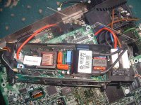
Here's a closeup of the optocouplers on power supply / e-ballast of the Proxima DS1. Hopefully this will explain what I did more easily.
The RED "A C" or "C A" are the LED side of the optocouplers, the GREEN "C E" or "E C" are the phototransistor side of the optocouplers.
I've also drawn in some of the PCB tracks (dark green) to make the connections clearer. The yellow LED is connected to the "sync" signal optocoupler PC1 (with resistor R1 bypassed).
The LED for the "lamp on" signal (normally on PC2) has been removed to make the photo clearer.
You can see that I've soldered across the "C E" pins of PC3 to force the projector to stay on ("lamp lit" signal to projector) as I intend to replace the ballast anyway. Now that I've found these signals, I could actually just chop the connector off the old ballast and short the wires together instead.....
Attachments
Oh, I forgot to add.... While I can short the pins on the Proxima DS1 ballast to force the projector on (old ballast broken), when I tried this with the Philips ballast from the Sanyo projector, the lamp lit for about 3 seconds, but went out again. This is probably because it requires a sync signal too.
I'm not sure which optocoupler does what yet, or what the signals are because the Sanyo projector itself is broken (opposite problem to the Proxima!). You can buy service manuals online for the Sanyo for $10, but I'm probably going to just sell this one anyway. I couldn't find a service manual or diagram for the Proxima DS1 though (it's quite old).
OzOnE.
OzOnE_2k3 said:Here's a closeup of the optocouplers on power supply / e-ballast of the Proxima DS1. Hopefully this will explain what I did more easily.
The RED "A C" or "C A" are the LED side of the optocouplers, the GREEN "C E" or "E C" are the phototransistor side of the optocouplers.
I've also drawn in some of the PCB tracks (dark green) to make the connections clearer. The yellow LED is connected to the "sync" signal optocoupler PC1 (with resistor R1 bypassed).
The LED for the "lamp on" signal (normally on PC2) has been removed to make the photo clearer.
You can see that I've soldered across the "C E" pins of PC3 to force the projector to stay on ("lamp lit" signal to projector) as I intend to replace the ballast anyway. Now that I've found these signals, I could actually just chop the connector off the old ballast and short the wires together instead.....
look my post. I know soldered too in other ballast.
@ywh, I'm probably going to sell the Sanyo projector (Philips ballast), but I need a lamp and ballast for the Proxima DS1. The original lamp is 270W but the projector is only rated at 600 ANSI lumens!. This is surprising, as the optics actually look quite good.
Do you think a 150W lamp and ballast would be good enough when using the projector in the dark? I'm willing to try it anyway.
Do you have a total price for the 150W lamp and ballast including the postage to the UK? I can send payment to 18wheeler once I have the total price. (don't mind JYd / JYs).
Also, my brother owns a bar in Thailand, and needs a lamp for a Sanyo PLC-XP10 projector. This is a 160W Metal Halide lamp, but I'm not sure if it's AC or DC as my brother doesn't want to open the projector at the moment because of the World Cup!
I can't find the XP10 in the replacement datasheet. It should be JYs (Metal Halide), is that right? Does anyone possibly know which lamp I need?
Also, what would be the total price for either one or two lamps for the Sanyo PLC-XP10, plus postage to Thailand?
Thanks,
OzOnE.
hi ywh, you've helped so many of us, thank you so much ! ")
OzOnE, please can you help me with overcoming the opto couplers in my infocus lp250 ?
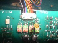
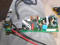
...i have included a picture of the ballast/lamp psu, it looks near identical to your sanyo one, and it also has opto-doodads with the code "SFH6106-1" and the label on the ballast says "EUC 150 A/00"
could you be so kind as to help me if you can ?
i am planning to light my pj with leds
led - yes you can !
many grovelling thanks in advance !
matt
OzOnE, please can you help me with overcoming the opto couplers in my infocus lp250 ?
...i have included a picture of the ballast/lamp psu, it looks near identical to your sanyo one, and it also has opto-doodads with the code "SFH6106-1" and the label on the ballast says "EUC 150 A/00"
could you be so kind as to help me if you can ?
i am planning to light my pj with leds
led - yes you can !
many grovelling thanks in advance !
matt
Attachments
Hi throwit,
Your ballast does look very similar to mine. It even looks like it uses the same chips (most definitely a Philips ballast). The pinout for the 5-pin connector on the Philips ballast from my Sanyo projector is as follows....
1.WHITE Collector of opto output
2.BLACK Emitter of opto output
3.BLACK Anode (shared)
4.BLACK Cathode of opto input 1
5.BLACK Cathode of opto input 2
If you're just trying to get your projector to stay on without the original ballast attached, you should be able to just short the first two pins on the cable. (I think this was the two opto contacts near the bottom of the "daughterboard".) Please check the connections to the optos first though, your ballast might be different to mine!
I'm very interested in the LED lamp thing, but I can't see how you'd ever get a bright enough picture. I would have thought anything decent would cost too much anyway?
OzOnE
hi OzOnE
thanks for your reply !
yeah, bit dicey really, leds, but i think the solution is somewhere...you may get thread fatigue, but perhaps have a read of my avforums thread (in my signature) - if you join that forum you can see the various pics of some of my ideas
biggest hurdle had looked like what you've sussed out, after that's overcome, i can try a few things to see what i get, starting with a basic lamp switch from uhp to led/removing some of the uv/ir filtration possibly, rangeing through to possible direct lighting at each lcd, to give something like a 500 lumen projector
cost may be as little as £150 for dimmable led lamps, or as little as £30 for a decent basic led lamp, i need to try a few things out before being too confident on cost
if i get you right, it seems that i may be able to take out the lamp psu altogether (something i had always hoped would be the case), if so, i'm happy to send you my lamp psu if it'll help you with your sanyo ...are you saying that the small connector/wires can be spliced appropriately to negate need for lamp psu (if i'm running my leds independantly from pj itself) ?
thanks for your reply !
yeah, bit dicey really, leds, but i think the solution is somewhere...you may get thread fatigue, but perhaps have a read of my avforums thread (in my signature) - if you join that forum you can see the various pics of some of my ideas
biggest hurdle had looked like what you've sussed out, after that's overcome, i can try a few things to see what i get, starting with a basic lamp switch from uhp to led/removing some of the uv/ir filtration possibly, rangeing through to possible direct lighting at each lcd, to give something like a 500 lumen projector
cost may be as little as £150 for dimmable led lamps, or as little as £30 for a decent basic led lamp, i need to try a few things out before being too confident on cost
if i get you right, it seems that i may be able to take out the lamp psu altogether (something i had always hoped would be the case), if so, i'm happy to send you my lamp psu if it'll help you with your sanyo
...are you saying that the small connector/wires can be spliced appropriately to negate need for lamp psu (if i'm running my leds independantly from pj itself) ?Attachments
...continued
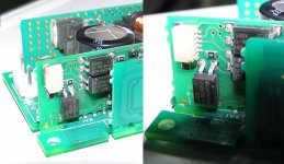
the small black wired 5 pin connection in the above picture plugs into the small white socket on the picture below, no white wire unfortunately, but it does all look very similar to yours
here is a close up picture of the opto isolators
many thanks for any help you can give
matt
the small black wired 5 pin connection in the above picture plugs into the small white socket on the picture below, no white wire unfortunately, but it does all look very similar to yours
here is a close up picture of the opto isolators
many thanks for any help you can give
matt
Attachments
throwit, the opto board on your InFocus is exactly the same as on my Philips ballast!
It should be easy peasy to get your projector to stay on without the original lamp ballast attached!.
I did read most of your previous posts on the other forums - Is this the same projector that you've wanted to remove the ballast from for ages?? Well, hopefully, this should help....
All you need to do is short the first two (top two) wires together which plug into the ballast. This MUST be the "lamp lit" signal to the projector, because you only have one opto pointing towards the connector (ie, to the projector mainboards). This should hopefully stop the projector from shutting down where it would normally have detected a lamp problem.
The other pins must be the "lamp on" and "sync" signals to the ballast. I should really try shorting both the other optos on my Philips ballast instead of one, it should stay on then. I'm selling the Sanyo PJ anyway though.
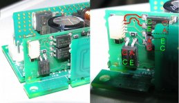
I've attached an edited photo of your ballast with the relavent pins highlighted in RED. To test this out (before cutting off any connectors!), just solder across the "C and E" pins of the top opto with a blob of solder or small piece of wire. You do NOT need to power your ballast btw!
If this works, and the projector stays on and behaves itself, you should be able to cut off the top two wires from the opto board and join them together. Then, just tape up the connector and remove the ballast!
I know the use of "C E" and "A C" is confusing, but I couldn't be bothered to draw the LED and phototransistor symbols!
Please note: some of you might have noticed that the "C and E" pins (Collector and Emitter) are swapped compared to the ballast in my previous posts - this is because the pinout actually differs between the optos. Here's the datasheet again for the SFH6106 optos....
http://www.vishay.com/docs/83666/83666.pdf
Regards,
OzOnE
It should be easy peasy to get your projector to stay on without the original lamp ballast attached!.
I did read most of your previous posts on the other forums - Is this the same projector that you've wanted to remove the ballast from for ages?? Well, hopefully, this should help....
All you need to do is short the first two (top two) wires together which plug into the ballast. This MUST be the "lamp lit" signal to the projector, because you only have one opto pointing towards the connector (ie, to the projector mainboards). This should hopefully stop the projector from shutting down where it would normally have detected a lamp problem.
The other pins must be the "lamp on" and "sync" signals to the ballast. I should really try shorting both the other optos on my Philips ballast instead of one, it should stay on then. I'm selling the Sanyo PJ anyway though.
I've attached an edited photo of your ballast with the relavent pins highlighted in RED. To test this out (before cutting off any connectors!), just solder across the "C and E" pins of the top opto with a blob of solder or small piece of wire. You do NOT need to power your ballast btw!
If this works, and the projector stays on and behaves itself, you should be able to cut off the top two wires from the opto board and join them together. Then, just tape up the connector and remove the ballast!
I know the use of "C E" and "A C" is confusing, but I couldn't be bothered to draw the LED and phototransistor symbols!
Please note: some of you might have noticed that the "C and E" pins (Collector and Emitter) are swapped compared to the ballast in my previous posts - this is because the pinout actually differs between the optos. Here's the datasheet again for the SFH6106 optos....
http://www.vishay.com/docs/83666/83666.pdf
Regards,
OzOnE
Attachments
sure thing, if i don't need it (just so happens i have two - a 150 watt (lp250) one, and a 132 watt (lp240) one, if you're round launceston way, you could collect, but let me figure this out first !
thank you so much for your help
yes, it's the same pj i've been banging on about forever !
will let you know how it turns out as soon as possible
matt
*strange, I have an email button on this page but you don't
thank you so much for your help
yes, it's the same pj i've been banging on about forever !
will let you know how it turns out as soon as possible
matt
*strange, I have an email button on this page but you don't
Ok, thanks matt, I've sorted email button now - I had "hide email" checked in my user cp.
I'm not in any hurry for a ballast, whenever you're sure you don't need one anymore.
Have fun with InFocus. Let me know if (when) it works.
What does it do if you disconnect the ballast atm? I'm guessing it spins the fans, then shuts down, yes?
OzOnE.
Edit: I want a proper smiley face damnit !
I'm not in any hurry for a ballast, whenever you're sure you don't need one anymore.
Have fun with InFocus. Let me know if (when) it works.
What does it do if you disconnect the ballast atm? I'm guessing it spins the fans, then shuts down, yes?
OzOnE.
Edit: I want a proper smiley face damnit !
don't have as much time as i'd like - too many piles of not done things !...but in the next few days i'll try it out, i plan to leave one pj going for a few hours without the ballast to see the longer term effects (which i hope will all be positive )
haven't had more than a few minutes of operation because of all these widgets...until next time !
i have a proper smiley face thanks to you
cheers mate
)haven't had more than a few minutes of operation because of all these widgets...until next time !
i have a proper smiley face thanks to you
cheers mate
- Status
- This old topic is closed. If you want to reopen this topic, contact a moderator using the "Report Post" button.
- Home
- General Interest
- Everything Else
- The Moving Image
- DIY Projectors
- I got my new lamp. It is for commercial projection use. people use it to replace the