Hello good fellas!
I ran into a problem and thought maybe some people here in diyaudio have experience on that hand to share.
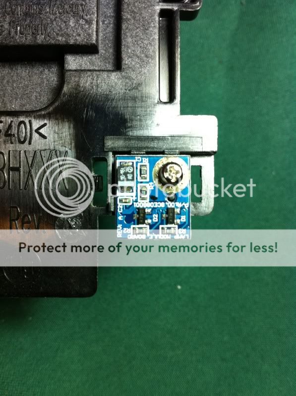
So I was retrofitting an Dell 4210X projector (I got it without an bulb module) to work with a LED. I guess I did bypass the lamp ballast already, tried different pins also just in case. So next I was looking at some strange board I found in the lamp module hole. It reads "LAMP TRANSFERRING BOARD". There are 4 pins that read GND, SCL, SDA and 5VSBY (standby?). There is no components and wires run back to mainboard.
The board looks like this:
[image]http://www.vanarebane.com/files/dlp_lamp_transferring_board.JPG[/image]
So my fair guess it, that basically, it seems that the lamp module as some sort of a chip that is connected to the mainboard via i2C interface. Maybe it's temperature sensor? Not so likely as there is one already. Probably a chip that stores hours that the lamp has worked? So when lamp is changed the counter is reset.
Now, buying a lamp is expensive and I would not like to go that way. It would be great if I had a broken lamp or even just the chip to probe it and somehow bypass that also.
Does anyone have experience with that lamp chip?
Could you please help me bypass it?
Thank you!
I ran into a problem and thought maybe some people here in diyaudio have experience on that hand to share.
So I was retrofitting an Dell 4210X projector (I got it without an bulb module) to work with a LED. I guess I did bypass the lamp ballast already, tried different pins also just in case. So next I was looking at some strange board I found in the lamp module hole. It reads "LAMP TRANSFERRING BOARD". There are 4 pins that read GND, SCL, SDA and 5VSBY (standby?). There is no components and wires run back to mainboard.
The board looks like this:
[image]http://www.vanarebane.com/files/dlp_lamp_transferring_board.JPG[/image]
So my fair guess it, that basically, it seems that the lamp module as some sort of a chip that is connected to the mainboard via i2C interface. Maybe it's temperature sensor? Not so likely as there is one already. Probably a chip that stores hours that the lamp has worked? So when lamp is changed the counter is reset.
Now, buying a lamp is expensive and I would not like to go that way. It would be great if I had a broken lamp or even just the chip to probe it and somehow bypass that also.
Does anyone have experience with that lamp chip?
Could you please help me bypass it?
Thank you!
Lamp module board info
I happen to have seen your post when I was looking for other info for the same projector. I figured since I had mine apart to help find the info that might help out. Keep us informed on your outcome. When my bulb burns out I may end up using some of your led conversion info. I'd love to see the picture results.
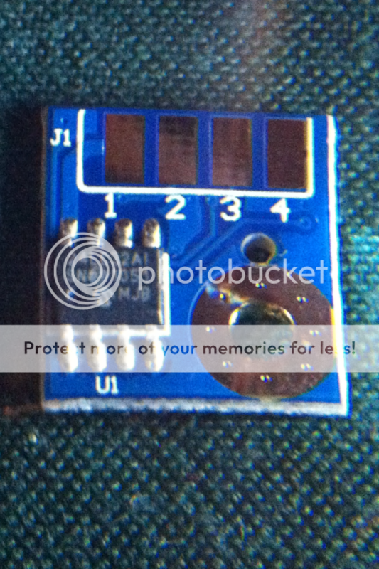
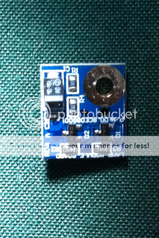
The board has printed a part number
P/N : 00.8CE08G001
The 8 pin IC chip
24LC32A1
Pins 1 and 4 on the ic chip go to J1 connector pin 4 and IC pin 5 goes to connector 1 the other two pins on the J1 connector 2 and 3 Im at a loss, their tied to the circuit on the other side of the board. That consists of 4 resistors, 2 capacitors and 2 transistors.
Perhaps with this general info you can find a basic circuit diagram online using the 24LC32A1 or similar chip. Good luck
I happen to have seen your post when I was looking for other info for the same projector. I figured since I had mine apart to help find the info that might help out. Keep us informed on your outcome. When my bulb burns out I may end up using some of your led conversion info. I'd love to see the picture results.
The board has printed a part number
P/N : 00.8CE08G001
The 8 pin IC chip
24LC32A1
Pins 1 and 4 on the ic chip go to J1 connector pin 4 and IC pin 5 goes to connector 1 the other two pins on the J1 connector 2 and 3 Im at a loss, their tied to the circuit on the other side of the board. That consists of 4 resistors, 2 capacitors and 2 transistors.
Perhaps with this general info you can find a basic circuit diagram online using the 24LC32A1 or similar chip. Good luck
The Lamp Module Board talks to the projectors uProcessor and will stop the ballast unit from damaging itself when there is no lamp fitted and stops people replacing just the lamp and not Dell's fitting. Similar to a diesel pump on a common rail engine, the pump is coded to work only with that engine. A new board is supplied with the new lamp and will probably need to be initialized to the uProcessor.
If the ballast supply fails, the projector will not work so replacing the lamp for a different type and removing/disabling the ballast will render the machine inoperable.
The "Sim card" type contacts marry up with a connector when the bulb is inserted.
A new lamp is around £135 in the UK, a new projector (from argos's ebay outlet) is around the same price and that is with a full 1 year warranty. A new lamp is not guaranteed as it is a consumable item but should be replaced if DOA.
I'm sorry to barge in here, but I've searched around like crazy and can't seem to find much info about Dell projectors. I have a Dell 4610X Projector which has white dots appearing all over the screen. I've read that the most likely problem is the DMD or DLP chip or whatever it's called, needs to be replaced.
So I've started taking apart the projector, got the lamp out real easily, I took out all the screws I could see around the body, but now I can't seem to get anything else apart. I don't want to force it and break anything, do you guys have any tips for getting the rest of this thing apart and getting to the DMD chip?
Any help or tips would be greatly appreciated.
Thanks!
Andy
disassembling 4220 Dell projector?
is there any insight on disassembling the 4xxx DELL projectors?
I have also removed all bottom screws, but that doesn't seem to be enough.
The lower part of the projector has some internal screws that seem accessible after the top cover is removed.
However removing the top cover doesn't seem straight forward.
is there anyone who can provide some insight?
thanks
The top cover was a hard one to take off as I remember. There was some hidden screws underneath some plastic cover on the top. So try to see if you can find any covers that seem to come off easily. I did breake my internal screw holders because I did not know how to open them.
The chip that creates image is, as I remember it correctly, mounted after the lens. The DLP light comes in from the right of the LCD like chip. I guess this is hard to fix and even expensive to buy replacement, but if you find a replacement, I guess you can fix this.
The chip that creates image is, as I remember it correctly, mounted after the lens. The DLP light comes in from the right of the LCD like chip. I guess this is hard to fix and even expensive to buy replacement, but if you find a replacement, I guess you can fix this.
- Status
- This old topic is closed. If you want to reopen this topic, contact a moderator using the "Report Post" button.