So I have checked out the commercial ballast bypass guide. But I'm posting here to see if I can get some help.
I have a hp cp6320 projector that I am adapting to use in a uv curing experiment. I was very carefully removed the things I do not need in the projector but left everything plugged in.
Projector
HP vp6320 Digital Multimedia DLP Projector in Bushwick, Brooklyn, NY, USA ~ Krrb
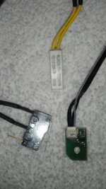
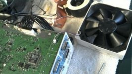
The obstacles that I have to trick are in the pictures below. It appears that there is a simple latch switch endstop, a temp sensor, a color wheel rpm sensor and of course there is thetricking of the ballast circuit on one of the 3d little square optocouplers circuits.
This thread talks about beating the latch and the thermostat sensor with a 2-3 ohm resistor.
http://www.diyaudio.com/forums/diy-...805-projector-into-thinking-lamp-present.html
- wondering if i can use the lines from a fan or something to plug into the resistor or would that mess something up? is there any powerline i can use?
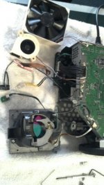
I needed to remove the color wheel completely because it blocks uv light and found that if i removed the whole bracket assembly that holds the color wheel and what appears to be an rpm sensor and have it off to one side it should defeat that mechanism.
The last questions I have:
- in the photo with the endstop the white block , is that really a temp sensor? and how would I go about putting a resitor on it? I have some resistors but what would I connect it to? Could i use some line from one of the fans for something?
- I broke off one of the fans, if i hold the broken off piece on the board it will spin when powered on but i think the connection is going to be too small for me to solder back on. The black wire to the fan is the connetor that does not have much left. should i risk trying to solder it back, or will the projector work without one of its fans? Or can i solder that black wire connection to somewhere easier on the board?
- And finally the ballast bypass. Unfortunately I do not have a lamp to check the voltage change. I was hoping someone would know which wires I should solder together.
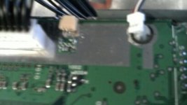
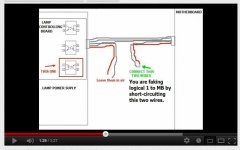
I have seen some people who solder 2 pins together on the board from the 4 wires coming from the area of the 3 optocouplers. I've seen someone cut two of those wires and connect them together- others just solder two of the optocupler connections together.
Fooling LCD Projector hack! Install any lightbulb! DIY - YouTube
I want to be very careful so I was hoping someone would tell me which method I should do, and which optocoupler or which wires I should cross
I have a hp cp6320 projector that I am adapting to use in a uv curing experiment. I was very carefully removed the things I do not need in the projector but left everything plugged in.
Projector
HP vp6320 Digital Multimedia DLP Projector in Bushwick, Brooklyn, NY, USA ~ Krrb
The obstacles that I have to trick are in the pictures below. It appears that there is a simple latch switch endstop, a temp sensor, a color wheel rpm sensor and of course there is thetricking of the ballast circuit on one of the 3d little square optocouplers circuits.
This thread talks about beating the latch and the thermostat sensor with a 2-3 ohm resistor.
http://www.diyaudio.com/forums/diy-...805-projector-into-thinking-lamp-present.html
- wondering if i can use the lines from a fan or something to plug into the resistor or would that mess something up? is there any powerline i can use?
I needed to remove the color wheel completely because it blocks uv light and found that if i removed the whole bracket assembly that holds the color wheel and what appears to be an rpm sensor and have it off to one side it should defeat that mechanism.
The last questions I have:
- in the photo with the endstop the white block , is that really a temp sensor? and how would I go about putting a resitor on it? I have some resistors but what would I connect it to? Could i use some line from one of the fans for something?
- I broke off one of the fans, if i hold the broken off piece on the board it will spin when powered on but i think the connection is going to be too small for me to solder back on. The black wire to the fan is the connetor that does not have much left. should i risk trying to solder it back, or will the projector work without one of its fans? Or can i solder that black wire connection to somewhere easier on the board?
- And finally the ballast bypass. Unfortunately I do not have a lamp to check the voltage change. I was hoping someone would know which wires I should solder together.
I have seen some people who solder 2 pins together on the board from the 4 wires coming from the area of the 3 optocouplers. I've seen someone cut two of those wires and connect them together- others just solder two of the optocupler connections together.
Fooling LCD Projector hack! Install any lightbulb! DIY - YouTube
I want to be very careful so I was hoping someone would tell me which method I should do, and which optocoupler or which wires I should cross
Attachments
Last edited:
these are the methods i have seen by bypass the optocouplers on various projector models. It looks like most models top most optocoupler is the one you need to bridge to trick the projector.
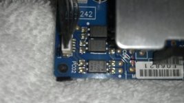
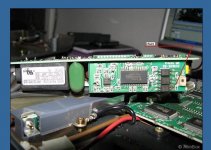
On my ballast there are 3 optocouplers you can see the top one is not aligned with the others. Is this the one i need to bridge the connections of?
Right now if i use something metal to bridge that optocoupler and turn on the projector, i get at first a flashing red temp light then after a few minutes the lamp and temp light will flash.
Lamp Warning Messages and Lights HP vp6320 Digital Projector - HP Customer Care (United States - English)
The flashing red temp light according to this guide means that the projector is too hot- but there is no bulb so its probably because its not detecting any heat.
I tried putting the temp sensor ( white block in post above) right next to my solder iron to get it warm to see if this would fool it, but it did not work.
the latch detection endstop should be fooled
the rpm color wheel detector should be fooled
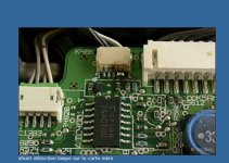
in the pic with the latch endstop and the temp sensor is another small circuit board is this a light detection sensor or something ?
Now its just fooling temp sensor and the optocoupler
On my ballast there are 3 optocouplers you can see the top one is not aligned with the others. Is this the one i need to bridge the connections of?
Right now if i use something metal to bridge that optocoupler and turn on the projector, i get at first a flashing red temp light then after a few minutes the lamp and temp light will flash.
Lamp Warning Messages and Lights HP vp6320 Digital Projector - HP Customer Care (United States - English)
The flashing red temp light according to this guide means that the projector is too hot- but there is no bulb so its probably because its not detecting any heat.
I tried putting the temp sensor ( white block in post above) right next to my solder iron to get it warm to see if this would fool it, but it did not work.
the latch detection endstop should be fooled
the rpm color wheel detector should be fooled
in the pic with the latch endstop and the temp sensor is another small circuit board is this a light detection sensor or something ?
Now its just fooling temp sensor and the optocoupler
Attachments
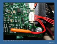
so I soldered the top most optocoupler two connections together which after a little tinkering around did stop the lamp red warning light from going off.
I now just have to fool the thermistor. it is a klixon 250v/7a ys11 model.
The little white box in the three sensors I have in the original post.
http://www.sensata.com/download/motor-ys11.pdf
i learned that a thermistor works by lowering its resistance as it heats up. the computer in the projector is reading this resistance and if its not low enough it knows the projector lamp is not on and if the resistance gets too low then it knows its over heating.
So you just need to know the resistance of this thermistor at the correct operating temp. Then put together the right number of resistors in place of the thermistor.
One problem is I don't have a lamp so i do not know at what temp to reference. I really need to find a data sheet on this thermistor but this is the closest thing I found.
was the link above.
so I have been attempting to record the resistance of this thermistor and its been a little confusing. with my ohm meter it fluctuates between .0 -.3 and that reading is pretty random and not constant even when i place the thermistor in boiling water to see if it changes with temp. (I'm doing something wrong i think) I tried varies resistors that measured .47 , 2.3, 5 , 9.2, 18, and 35 in ohms. had no success.
I think the resistor change in the thermistor is really small. because its seems to take the projector longer to fail the lower ohms i put in as a resistor. I actually thought i had the problem solved when i just put in a small capacitor with a low and very fluctuating resistance of ohms in place of a normal resistor and it worked. I was able to turn the projector on and off and let it run for 5 mins several times and it seemed to fix the problem with bypassing the temp sensor.
But after a while it stopped working. going in to the electronic store tomorrow to see if they can help me with this thermistor.
I just need the right ohms of resistance to make it think its at operating temperature.
There are two temp sensors. one is a safety switch that just turns off if the lamp gets too hot. the other is a 4 wire temp sensor board. it uses a resistor that changes with temp. so far no success in placing it near heat sources to see if i can duplicate the temp where it thinks it is operational. older projectors use a two wire thermistor which have been able to be fooled with a simple 2-3 ohm resistor put in place. the four wire has been more difficult to figure out.
Found out that the color wheel sensor needs light on it for it work properly.
Flickr: CGIAnimated's Photostream has some photos of the temp sensor board.
So far it looks like only a few types of projectors have been able to be modded.
I'm pretty disappointed In the diy audio community so far. this request for help has turned into a blog. Anyway I thought I would at least try and help the people who stumble on this thread looking for how to mod a projector.
Here is a list of links to the successfully modifiable projectors i have found.
Gigaware Micro Projector LED lamp Upgrade Replacement Repair. - YouTube
Porta photo album
Porta photo album
Porta photo album
http://www.diyaudio.com/forums/diy-projectors/128494-infocus-x1-x2-lamp-ballast-bypass-2.html
projectionforums.com • View forum - Ballast Bypass
InFocus LP600 Bypass lamp check
MODDING
http://www.diyaudio.com/forums/diy-...805-projector-into-thinking-lamp-present.html
http://www.diyaudio.com/forums/diy-...in72-projector-into-thinking-bulb-inside.html
- Status
- This old topic is closed. If you want to reopen this topic, contact a moderator using the "Report Post" button.
- Home
- General Interest
- Everything Else
- The Moving Image
- DIY Projectors
- Lamp bypass? hp vp6320 Pics