Hey Mark, if you hold the projector on your lap with the middle fan facing away from you with the lens also facing forward the bottom left of the chip is what you are looking for
ic4811
3[ ]
2[ ]
1[ 0 ]
I hope the diagram helps the 0 is the bottom of chip the ie circle depression and the 123 is where the pins start so looking at it bottom left side the 3rd pin up.
ic4811
3[ ]
2[ ]
1[ 0 ]
I hope the diagram helps the 0 is the bottom of chip the ie circle depression and the 123 is where the pins start so looking at it bottom left side the 3rd pin up.
Sorry if i'm making a mess but i still dont understand.
Please Spirit,consider this...
I have the board positioned so i can read the chip writings,this means that the projector is with the power lead pointing at me and the focusing lens is at me right side.
Now this means the chip's small circle depression is at the botoom and left side,now is the pin also on the bottom like the small circle?And is it on the left side like also the circle?
Waiting,thank you.
_l__l__l__l__l__l__l__l__l__l_ <-------- top!!
l ............................................. l
l ............................................. l
l ............................................. l
l ...... o............................ 45A l
--------------------------- <---------bottom!!
l ... l ...3 .. l .. l ... l .. l .. l .. l ... l
The other darwing got all ruined,hope this drwaing gets better.
The number ones are the pins(10 pins) the number 0 is the small circle with a depression and the number 3 is the pin to cut.
Is this right?
l ............................................. l
l ............................................. l
l ............................................. l
l ...... o............................ 45A l
--------------------------- <---------bottom!!
l ... l ...3 .. l .. l ... l .. l .. l .. l ... l
The other darwing got all ruined,hope this drwaing gets better.
The number ones are the pins(10 pins) the number 0 is the small circle with a depression and the number 3 is the pin to cut.
Is this right?
I understood already from your previous diagram.
I did the hack but didnt work,the problem is not the hack,the projector already had a problem,he was showing a red led of warning,the power turns green the lamp replace turns light orange and then the power turns red the projector shuts down and the warning light comes on,all this before the hack,after the hack the same symptoms,nothing has changed.
I was looking for this hack not only for the lamp mod but also to try to bypass the use of the ballast in which the fail might have been,but i guess since the problem persists its most likely to be in the mainboard.I have two of these xu41 projectors and both suffer from the same,one i get the light warning error and the small fan near the video plugs on the back doesnt turn on and i know the fan is ok because it works on the second projector.The second projector,the one i've made your hack same light showing and the so called middle fan on the front doesnt work and i also tested that fan and the fan is ok.I think the power circuitry to the fans in the board are defective or maybe its the power block itself.My bad luck. : ( -I did register on this site just for this hack....damn.
Thank you very much Metaspirit,you have my respect for that hack of yours because its not a regular hack,i can imagine how difficult must have been to test connections in a chip like that and even finding the culprit component responsable for signalling the lamp to the board.
Thank you very much.
I guess it is a motherboard fail
can somebody help me? I have an EPSON EB-1900 and I can´t bypass the ballast. I´ve done this in the past but it seems like i´m doing something wrong now .3.
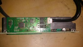
I attach a photo of the ballast.
I´ve tried to make a bridge between pins 3 and 4 of The optocoupler below and it gives me a red light error wich according to the manual it´s the death xD. So I unsoldered it and tried with pins 3 and 4 of the middle one, and same thing. Same thing with the top one. Where do I have to make the bridge?
I hope somebody can help me. I´ve done a bit of work in this projector. I installed a 100w 11000 lumen led inside... XD If I get it working It would be AWESOME XD But for the moment all I can see it´s EPSON logo and then lamp error...
Thanks
Attachments
maybe?
I have this too...I am going to short out the yellow and black...pin 5 and 1..will let all know if success or it blows up !
I wonder if someone bypassed the ballast on Acer h6510bd 1080p dlp ? I just bought it but plan to replace the bulb with led as soon as it reaches 4000 hours.
If someone can find a service manual it'd be great")
I have this too...I am going to short out the yellow and black...pin 5 and 1..will let all know if success or it blows up !
Hi, for Optoma 752 dlp I already make ardunio code to bypass the ballast and it works. This projector works with osram ballast PT-VIP-03MID.
See here the code:????? ??????! ???????? ????????? ???????? ????? ????????? Epson. (???????? 6) / ?????????? ??????? / ????? arduino.ua
But attention on interface that you do. You need to respect the ballast configuration of optocuplers and after that connect to arduino or other.
I hope that somebody will find this information useful.
Also in this site it is code for another model of osram ballast.
infocus lp530 need help
Dear sir
I have infocus lp530 without bulb Please guide me how to bypass lamp
I have also these to use
1. Original Reflector
2. Halogen bulb ( 55w 12v dc, ( 100w 24v dc ))
3. xenon bulb ( 100w , 12v dc)
4. Atx power supply
5. Laptop power supplies ( 12v , 16v , 19v )
please guide
Dear sir
I have infocus lp530 without bulb Please guide me how to bypass lamp
I have also these to use
1. Original Reflector
2. Halogen bulb ( 55w 12v dc, ( 100w 24v dc ))
3. xenon bulb ( 100w , 12v dc)
4. Atx power supply
5. Laptop power supplies ( 12v , 16v , 19v )
please guide
Hi Sir , can you help me for toshiba DLP T90 circuit digram or connection
The lamp is getting on /off then it on lamp led turn to red after that it went to standby.
even pls let me know how to check the the projector is working or not.
I HV tried all possible like show in web short optocupler, or main board wire shorting etc connections but not able to bypass lamp with projector pls reply or email me soon.
Thanks
Hi Sir , can you help me for toshiba DLP T90 circuit digram or connection
The lamp is getting on /off then it on lamp led turn to red after that it went to standby.
even pls let me know how to check the the projector is working or not.
I HV tried all possible like show in web short optocupler, or main board wire shorting etc connections but not able to bypass lamp with projector pls reply or email me soon.
Please help
I have infocus lp530 without bulb Please guide me how to bypass lamp
I have also these to use
1. Original Reflector
2. Halogen bulb ( 55w 12v dc, ( 100w 24v dc ))
3. xenon bulb ( 100w , 12v dc)
4. Atx power supply
5. Laptop power supplies ( 12v , 16v , 19v )
please guide
I have infocus lp530 without bulb Please guide me how to bypass lamp
I have also these to use
1. Original Reflector
2. Halogen bulb ( 55w 12v dc, ( 100w 24v dc ))
3. xenon bulb ( 100w , 12v dc)
4. Atx power supply
5. Laptop power supplies ( 12v , 16v , 19v )
please guide
Hi, for Optoma 752 dlp I already make ardunio code to bypass the ballast and it works. This projector works with osram ballast PT-VIP-03MID.
See here the code:????? ??????! ???????? ????????? ???????? ????? ????????? Epson. (???????? 6) / ?????????? ??????? / ????? arduino.ua
But attention on interface that you do. You need to respect the ballast configuration of optocuplers and after that connect to arduino or other.
I hope that somebody will find this information useful.
Also in this site it is code for another model of osram ballast.
Hello! I've registered on this forum just for say thank you very much!. The code works for an Arduino Nano clone, and the mentioned ballast.
The circuit for optocouplers from the arduino.ua forum also works. Just as you said, we need to know the I/O from SCI connector to the mainboard (Tx, Rx, GND and Vcc).
My model is a Vivitek D825ES. Internally it's just like a Optoma TX735 (without HDMI) with Osram VIP 03 ballast.
And again, thanks a lot. Greetings from Chile!
Last edited:
Simply outstanding!!!! I have a Panasonic ptae100 and will attempt to follow these directions. Will post pictures as a learning experience for all.
- Home
- General Interest
- Everything Else
- The Moving Image
- DIY Projectors
- Commercial Projector Ballast Bypass Guide