Just got an Infocus LP725 projector from ebay today with a blown lamp, I was thinking about replace the lamp with a 20w led. Right now looking for a way to bypass the lamp check. I've read quite a lot of posts about the same issue but not quite get it, when I'm actually take apart of the projector, I was frightened by the complexity of this projector don't know where to start.
Is there any one who have the experience of fooling the Infocus lp725?
Is there any one who have the experience of fooling the Infocus lp725?
I don't have experience with that projector... but I just did my own DIY relamping on an Epson Powerlite.
Just in case you don't know how these typically work, here's an overview of the important stuff in a typical projector:
Power supply
Ballast
Bulb
Mainboard
Optical Assembly and maybe some misc electronics
LCD(s) or DLP stuff
The last 2 things might not be separate boards and stuff but the important part is the power supply and ballast.
A ballast is a big component that may or may not be mounted on it's own board. A ballast is important for starting any metal halide bulb. Florescent tend to need one too. This is because in a gas-filled bulb, you need to generate a spark across the gas or something to make it start. A spark jump takes alot of volts, and the ballast helps to do that. It doesn't use much power once the bulb's started.
It's like matches. You need to apply force to the match head to ignite it, and once it's lit, you don't need to apply any more force.
Anyways, look for the ballast. It makes a buzzing sound when trying to start the bulb, even if the bulb isn't in there. Hope that it's on a separate board... otherwise you won't be able to separate it's operation from the rest of the thing.
I suggest putting the broken bulb in when looking for it. Hopefully you DID save it. I found that the bulb carriage on mine had a little board on it that bridged these two contacts when inserted. It didn't seem to make a difference, but it means something. There was a big 2-wire connector that went to the ballast also.
So if you find that ballast board, find the connections coming out of it. You should find a BIG 2 wire plug going to the bulb, a BIG 2 wire plug coming from another board, and a small-wire multi-wire connector coming from the main board.
Generally the rule of thumb is "look for the control wires". The control wires are the things to trick.
I have seen people do stuff like connect some wires from that control plug, but they didn't explain why.
Others say just find some wire in that and ground it.
In MY case, I had a 3-wire plug coming off of the mainboard. I tested for current between each of the three. I also measured volts. I soon discovered which was the negative return wire.
A few tiny amps flow through the thing when it's trying to start the bulb. My meter put a resistive load on it, so the ballast wouldn't go when the meter was connected.
Then I tried grounding either of the hot wires through my meter while measuring amps. One of them made it work. It wasn't showing any amp reading on my meter though. This was because the measuring scale was putting enough resistance on the line to make it think it was connected.
After I realized what was going on, I realized that I just needed to put a resistor in-line with that pin and then ground it. I desoldered a 42 ohm resistor from a junk power supply and hoped it was enough. It happened to be enough... so joy!
OKAY - that's alot of crap to read but here's what I say you do.
EITHER get a meter that has a 10A load line (this is a common feature for multimeters, get it at RadioShack. Mine was $5 at a discount store) OR get a resistor and wire, and test grounding the pins. However the latter method could be a quick way to getting yourself killed, especially if you pick the wrong wire to test. There is high voltage in many places in a projector. The amps is what kills you though.
A meter is recommended.
If this all goes way over your head, then i've heard that there is such a thing as "diy companies" who could help. There may be some users on this forum who could do it too.
Thanks Shorin, thanks for the detailed reply. It really gives me an idea of what I'm going to do.
I have took the PSU apart and found the ballast there, below is the link to my on-line photo album where u can find all the photos about the projector.
I've go through an post about use opto-couplings to fool the projector, but the funny thing for me is I even can't find the optos. I do find 2 pairs of 4 legged chips on the PSU board which can be found on my web album.
Still going through the PSU, but need leaving for the university soon
Ok to sum up before leave.
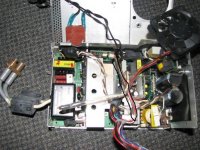
The PSU have 2 PCBs, one is the power supply for the main board(the right half), the other half is for the lamp I guess. There are 3 wires form the left half goes to the main board which u can see from the attached photo. So according what you said the 3 wires should be the ones doing the trick.
Thanks for advance any help will be appreciated

I have took the PSU apart and found the ballast there, below is the link to my on-line photo album where u can find all the photos about the projector.
I've go through an post about use opto-couplings to fool the projector, but the funny thing for me is I even can't find the optos. I do find 2 pairs of 4 legged chips on the PSU board which can be found on my web album.
Still going through the PSU, but need leaving for the university soon
Ok to sum up before leave.
The PSU have 2 PCBs, one is the power supply for the main board(the right half), the other half is for the lamp I guess. There are 3 wires form the left half goes to the main board which u can see from the attached photo. So according what you said the 3 wires should be the ones doing the trick.
Thanks for advance any help will be appreciated
Attachments
forgot to post the link to my web album
below is the link to my web albums
http://picasaweb.google.com/donghui2k7
below is the link to my web albums
http://picasaweb.google.com/donghui2k7
I think I'm nearly there after reading this post http://www.diyaudio.com/forums/showthread.php?s=&threadid=29735&perpage=25&pagenumber=1
I think all what I need to do is to shortcut the red and black wires from the ballast board to the main board, but before I'm doing that I'm worried about the lethal voltage from the ballast. Anyone reckon it will still doing the trick without the power supply to the ballast board?
I think all what I need to do is to shortcut the red and black wires from the ballast board to the main board, but before I'm doing that I'm worried about the lethal voltage from the ballast. Anyone reckon it will still doing the trick without the power supply to the ballast board?
almost there!!
You're almost there.
If you read alot of that post, you would have learned that all that stuff about optocouplers. Optocouplers are apparently a way to get a "signal" without being connected to the circuit. There's a light inside those chips and half the leads connect to one circuit and half to another, and there is no connection in between. This pretty much means those 3 wires are probably not part of the ballast PSU circuit, but electrically separated because of the optocouplers.
Don't worry about the voltage here, those 3 wires should be safe. Large amounts of current (amps) is what is deadly and high current needs thick wire.
Either way, get yourself a multimeter so you know what you're doing.
You can do your tests with those 3 wires disconnected from the ballast PSU, or just disconnect the ballast board from the main PSU (look for the big wires, I think it's the 2 twisted ones that go from one side of the board to the other).
Ideally once you get this working, it would be good to leave the ballast disconnected permanently. This would prevent wear on that circuit, and decrease heat I guess. I heard that it could be bad for a power supply (the main one in this case) to not have a load on it... You'd have to put some sort of resistor (or a crap load of resistors) on the old ballast line to remedy this.
I didn't bother, I just left the ballast board disconnected. I'll find out the truth if and when my projector PSU dies.
warning
I wouldn't do this. Running current/voltage to a place where it shouldn't go sounds like a pretty bad idea to me. I might try it if I didn't have anything else that worked, but I would rather hook up a small amount of voltage to it (a.k.a an itty battery grounded to the case) to try to signal it. Another way would be to somehow vary the current or volts across the jump.
It wouldn't be a big deal if the other wire was DEFINITELY ground.
I would try the grounding method first. It would probably have the same effect.
I think all what I need to do is to shortcut the red and black wires from the ballast board to the main board
I wouldn't do this. Running current/voltage to a place where it shouldn't go sounds like a pretty bad idea to me. I might try it if I didn't have anything else that worked, but I would rather hook up a small amount of voltage to it (a.k.a an itty battery grounded to the case) to try to signal it. Another way would be to somehow vary the current or volts across the jump.
It wouldn't be a big deal if the other wire was DEFINITELY ground.
I would try the grounding method first. It would probably have the same effect.
Did that tonight but still can't tell if it works or not. I have put a led camping head light into the lamp housing, before the pj get started I can see a bright square area on my wall,after I turn on the pj about 5 seconds the bright area turning dim and I can't see any words and whatsoever on it. Don't know if I just screw the whole thing up, I think I suppose to see a pure green picture.
after I turn on the pj about 5 seconds the bright area turning dim and I can't see any words and whatsoever on it.
It getting dim without you turning that light off means the LCD screen came on. Your lamp may not be bright enough to illuminate the thing.
What I did was i pointed the open bulb chamber at a house light and looked through the lens. That worked well enough, even with my 3-LCD version.
Hook up a video source or a VGA signal to confirm a signal.
I really already knew it was working by the indicators and fans coming on instead of the bulb light blinking.
OH... did you put a resistive LOAD on that ground? It didn't work without that for my projector.
Man I did it, it works right now. I was watching the daily show on my wall last night that is so amazing.
What I did is simply ground the +5 red wire without any resistance, it works fine right now what I need to do next is looking for the lighting source. My options are the CREE led maybe 6 of them, or just buy a 20w led which gonna cost me AUD$50. I think I might go for the 20w led one need to mail order it from China.
Thanks again for all your replies man!! I can watch the Olympic on my ceiling now
heh heh.... olympics on the cieling...
You may think that you're done, but the hard work is just beginning.
I dunno what you want to do (keep the bulb in the projector or out of it somehow) and I guess it doesn't matter. But the important thing is - it needs to be bright enough to use in the daytime.
Sure, it works in a pitch black room with a flashlight for a bulb, but I have had eye strain every night I use my projector. Totally bad. My eyes are still kinda screwed up from it right now (either that or it could be something else going around (sickness)).
Anyways, yeah, make sure you build the thing so that you can see it in the daylight.
Also make sure the bulb chamber gets cool enough. I heard that if you have a lens right there, it could crack from the heat of halogen bulbs. (automotive type).
You should have a temperature sensor shut the projector down if things get too hot. If that keeps happening then you need to put in another fan or something.
Anyways - good luck!
Another bulb
You guys might try these bulbs there cheap and look like they might fit in the projector unit. It will require an alternate power supply, also the color temp. might be an issue.
http://www.bulbtown.com/ProductDetails.asp?ProductCode=A-6519&Show=ExtInfo
You guys might try these bulbs there cheap and look like they might fit in the projector unit. It will require an alternate power supply, also the color temp. might be an issue.
http://www.bulbtown.com/ProductDetails.asp?ProductCode=A-6519&Show=ExtInfo
Re: Another bulb
Looks neat... mmm... I dunno about it. It could be tough because you need a 28V power supply. I guess you can add up the wires on a PC power supply to get you close but you would still be a little under. Also, I'm not sure if you can do that to add voltages. (don't try it yet !)
synchronous said:You guys might try these bulbs there cheap and look like they might fit in the projector unit. It will require an alternate power supply, also the color temp. might be an issue.
http://www.bulbtown.com/ProductDetails.asp?ProductCode=A-6519&Show=ExtInfo
Looks neat... mmm... I dunno about it. It could be tough because you need a 28V power supply. I guess you can add up the wires on a PC power supply to get you close but you would still be a little under. Also, I'm not sure if you can do that to add voltages. (don't try it yet !)
I've placed my order yesterday from a seller in China, I ordered 4 CREE q2, another 4 red and green 3w led and half dozen of 1w white led and a lot of other stuffs which I even can't remember.
Will receive that next week hopefully.
Actually there's a group of people in China using the HIDs which used for the car front lights as the lighting source, actually that looks awesome but kind of too big to fit in in a commercial projector lighting house.
Will receive that next week hopefully.
Actually there's a group of people in China using the HIDs which used for the car front lights as the lighting source, actually that looks awesome but kind of too big to fit in in a commercial projector lighting house.
leds
I've done some research, apparently LEDs are not measured in lumen s or candle power, or wattage, hence my confusion. This rather simple website filled me in on the details.
http://www.gizmology.net/LEDs.htm
as a side note I've also found these LEDs which seem to be slightly more generic then Cree made by Phillips
http://www.luxeon.com/solutions/solution.cfm?id=2
these Luxeon LEDs can be purchased easil on EBAY through
http://www.sureelectronics.net
They are also a Chinese company (actually distributors) and they seem to be quite dependable. As a side note I think you would need at least 25 of them in series to produce enough light to power an average projector. There rated at about 80 Lumens a piece. Please don't forget that you're projectors are all rated at there light output, and not input. So you may want to go double the Lumen rating of you're projector.
So there's my two cents, as a side note the sure website above also has schematics for wiring LEDS.
Thanks for the information,man!
I'm not expecting using the LEDs to achieve the same rating of the lamp, all I want is reasonably bright and don't need to bother with the heat. So LED comes to my first choice. The LEDs I'm going to use are the CREE q2 which under 700ma goes up to 141.6-152.1 Lumens. Besides that I got some colored LED and 1w white LEDs as well, I'm pretty sure I can use that with my light on.
If I have the money I'll definitely go for the OSRAM ostar series the most powerful one in the range can up to 50w which capable of generate 3500 Lumens but that thing is bloody expensive. But there's 20w one which generates 1000 Lumens costs about AUD$90. You can find all these great LEDs on the link below.
http://catalog.osram-os.com/catalogue/catalogue.do?favOid=000000010001fefb00550023&act=showBookmark
- Status
- This old topic is closed. If you want to reopen this topic, contact a moderator using the "Report Post" button.
- Home
- General Interest
- Everything Else
- The Moving Image
- DIY Projectors
- Need help of how to bypass the lamp check of Infocus LP725